
Page 21 - Kabeldon
P. 21
Standard
switching devices
Utilization category The torque range depends on the conductor cross-section,
The utilization category for the switching devices is stated in please see “Technical data” or installation instructions.
the “Technical data” for each product. Normally it’s no need to any retightening but it may be
required in special situations, i.e. when a short-circuit has 2
Rated diversity factor happened.
For switching devices mounted in a cable distribution
cabinet, distribution board or directly on the wall; the rated Area range
current must be reduced where there are parallel current The stated area range refers to connection with a stranded
paths. or solid conductor. When connecting a flexible conductor,
reduce the max. area by one area step.
Number of main circuits Rated diversity factor
2 and 3 0.9 Parallel conductors
4 and 5 0.8 The connectable area for parallel conductors is determined
6-9 0.7 by dividing the maximum area by the number of parallel
10 and above 0.6 conductors and reducing by one more area step.
Rated current for phase- and neutral busbars. Ex: max cable connection 300 mm², 300/2 150 go down
The stated rated current refers to the highest permitted by a step 120.
current in any section of the busbar.
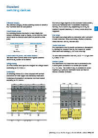
Modular system
Voltage testing The dimensions of all items that can be connected to the
All of the devices have apertures designed for voltage testers busbar system are based on a module (one module
conforming to IEC 61243-3. M = 12.5 mm). This makes it easy to calculate the space
required by a particular distribution board and then to
Connectors choose a suitable enclosure.
All switching devices SLD come complete with terminal
connectors for both copper and aluminium conductors.
Connectors for aluminium conductors have been tested
according to IEC 61238-1.
10 M 4 M 12 M
| Switching devices | Kabeldon fusegear and cable distribution cabinets | 2016 | 2/4