
Page 601 - Entrelec Terminal Blocks Master Catalog
P. 601
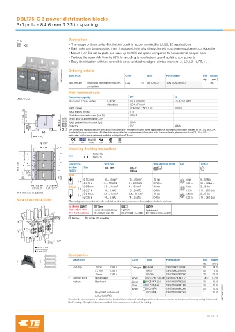
DBL175-C-3 power distribution blocks
          3x1 pole - 84.6 mm 3.33 in spacing


                                    Description
             X3                     • The usage of three poles distribution block is recommended for L1, L2, L3 applications
                                    • Each pole can be separated from the assembly to align the poles with upstream equipment configuration
                                    • Mount it on Din rail or plate and save up to 50% rail space compared to conventional copper bars
                                    • Reduce the assembly time by 80% by avoiding to use fastening and isolating components
                                    • Easy identification with the reversible cover and delivered pre-printed markers L1, L2, L3, N, PE, +, –.

                                1SNC166050V0014  Ordering details  Color   Type      Part Number        Pkg Weight
                                    Description
                                                                                                            1 pce g
                                                                                                        qty
                                             Three poles distribution block 3x8
                                    Feed-through
                                             connections         Grey      DBL175-C-3  1SNL317531R0000  1  360
                                    Main technical data
                                    Connecting capacity            IEC                   UL
          DBL175-C-3
                                    Max current / Cross section  Copper  175 A / 70 mm²  175 A / 2/0 AWG
                                                        Aluminium  135 A / 70 mm²
                                    Rated voltage                  1000 V AC / 1500 V DC  1000 V
             32.5  1.28"  25  0.98"  Rated impulse voltage         8 kV
                                    Short-time withstand current (Icw 1s)
                                                                   6000 A
                               50.7  2"  59.8  2.35"  52.3  2.06"  Short Circuit Current Rating (SCCR)  30 kA
                                    Rated peak withstand current (Ipk)
               23.5    0.93"        Protection                     IP10                  NEMA 1
                                    The connecting capacity data for one Rigid: Solid/Stranded - Flexible conductor (when applicable) is a mandatory information required by IEC, UL and CSA
                                    standards (Copper conductors). All other data are provided as supplementary information only. For more details, please consult our CB, UL or CSA
                  36.3  1.43"       certificates and technical datasheet available on http://www.TE.com
                     75  2.95"        CE  CB  RoHS  USR  CSA  EAC
                     62  2.44"  5  0.2"
                                    Mounting & wiring instructions
               =                =               TH 35-7.5,
             =                      Rail         TH 35-15
          84.6  3.33"  =  =     =   Connection  Size     Wire type             Wire stripping length  Tool  Torque
                                    Number
                                    by pole
             28.2  1.11"  14.7  0.58"  10.7    0.42"  Input
                                        1x  Ø 11.8 mm  16 ... 50 mm²  16 ... 70 mm²  18 mm     5 mm    6... 10 Nm
                                           Ø 0.46 in  8 ... 1/0 AWG  6 ... 2/0 AWG  0.708 in   0.20 in  53 ... 88 lb.in
                 9.5 x 5.5 mm  12 x 5.5 mm  Output  Ø 6.8 mm  2.5 ... 16 mm²  6 ... 16 mm²  11 mm  3 mm  2 ... 3 Nm
                 0.37 x 0.22"  0.47 x 0.22"  1x
                                           Ø 0.27 in  14 ... 6 AWG  10 ... 6 AWG  0.43 in      0.12 in  18 ... 26.5 lb.in
          84.6 mm 3.33 in spacing          Ø 6.4 mm   2.5 ... 16 mm²  2.5 ... 16 mm²  11 mm    5.5 mm  2 ... 3 Nm
                                        6x
                                           Ø 0.25 in  14 ... 6 AWG  14 ... 6 AWG  0.43 in      0.22 in  18 ... 26.5 lb.in
          Mounting instructions
                                    When using maximum cable size with insulated ferrules, use a maximum of 2 non-adjacent holes in each row.
                                    Not allowed
                                    Flexible without ferrule  Flexible with insulated ferrule   Rigid Solid   Rigid stranded
                                    (IEC V-K & UL: class 5/6)  (IEC V-K & UL: class 5/6)  (IEC V-U class 1, UL solid)  (IEC V-R class 2, UL class B/C)
                                        Allen key      Posidriv - flat screwdriver


                          5.5 mm  0.22"
                          PZ2
                    3 mm  0.12"
                    5 mm  0.16"
                                    Accessories
                                      Description                   Color  Type      Part Number        Pkg  Weight
          1          2
                                                                                                        qty  1 pce  g
                                    1  End stops  10 mm   0.394 in  Dark grey  BAM4  1SNK900001R0000    50   14.00
                                                 5.2 mm   0.205 in         BAZ1      1SNK900002R0000    50   5.30
                                                 10 mm   0.394 in          BAZH1     1SNK900102R0000    20   24.00
                                    2  Terminal block   Blank marker  White  MG-CPM 13 41790 1SNB041790R0512  1960  0.236
                                      markers    Blank card         Green  MC512PA-GN  1SNK149997R0000  20   10.00
                                                                    Blue   MC512PA-BL  1SNK149998R0000  20   10.00
                                                                    White  MC512PA   1SNK149999R0000    20   10.00
                                                 Pre-printed marker card   MC512PA   1SNK149002R0000    1    10.00  1SNC166021S0201
                                                 (L1-L2-L3-N-PE)
                                    Complete list of accessories is indicated in the terminal block datasheet including end stops. Some accessories such as jumper bars may modify the terminal
                                    block's ratings: Complete information available in the accessories section of the catalog.


                                                                                                          PAGE 13