
Page 490 - Motor protection and control Manual motor starters, contactors and overload relays
P. 490
3/416 ABB MOTOR PROTECTION AND CONTROL
—
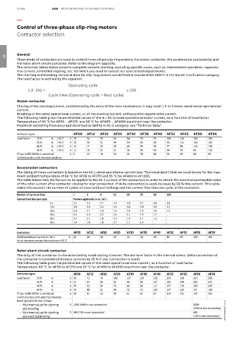
Control of three-phase slip-ring motors
Contactor selection
General
Three kinds of contactors are used to control three-phase slip-ring motors: the stator contactor, the acceleration contactor(s) and
03
the rotor short-circuit contactor. Refer to the diagram opposite.
The selection tables below concern complete smooth starting, excluding specific cases, such as: intermittent operation, regenera-
tive current, controlled slipping, etc. for which you need to consult our specialised departments.
The starting and breaking technical data for slip-ring motors are defined in standard IEC 60947-4-1 in the AC-2 utilization category.
The load factor is defined by the equation:
Operating cycle
L.F. (%) = x 100
Cycle time (Operating cycle + Rest cycle)
Stator contactor
Closing of the starting current, conditioned by the value of the rotor resistances: it may reach 1.5 to 4 times rated motor operational
current.
Breaking of the rated operational current, or of the starting current, with possible regenerative current.
The following table gives the permissible values of the Ie / AC-2 rated operational stator current, as a function of load factor.
Temperature of 60 °C for AF09 ... AF370 and 55 °C for AF400 ... AF1650 maximum near the contactor.
Maximum switching frequency and electrical durability in AC-2 category: see "Technical data".
Contactor types AF09 AF12 AF16 AF26 AF30 AF38 AF40 AF52 AF65 AF80 AF96
Load factor 15 % Ie / AC-2 A 18 24 33 52 64 76 79 106 124 154 184
25 % Ie / AC-2 A 15 20 31 44 54 65 68 90 111 136 163
40 % Ie / AC-2 A 13 17 26 38 46 55 58 77 94 116 139
60 % Ie / AC-2 A 11 14 22 31 38 46 48 64 78 96 115
S7 acc. to IEC 60034-1: periodical A 9 12 18 26 32 38 40 53 65 80 96
continuous duty with electrical breaking
Acceleration contactors
The sizing of these contactors is based on the AC-1 rated operational current (see "Technical data") that we recall below for the max-
imum ambient temperature of 60 °C for AF09 to AF370 and 55 °C for AF400 to AF1650.
The table below lists the factors to be applied to the AC-1 current of the contactors in order to obtain the maximal permissible value
of the rotor current after contactor closing for star connection. If delta connection is used, increase by 50 % this current. This table
takes into account the number of cycles an hour (without inching) and the current flow time per cycle, in the contactor.
Number of cycles an hour 1 3 6 12 20 30 60 120
Current flow time per cycle Factors applicable to Ie / AC-1
5 s 5.2 4.9 4.7 4.3 4.0 3.7 3.4 2.8
10 s 3.8 3.6 3.4 3.1 3.0 2.8 2.6 2.2
20 s 2.8 2.7 2.6 2.5 2.4 2.2 2.0 1.6
30 s 2.4 2.3 2.2 2.1 2.1 1.9 1.7 -
40 s 2.2 2.1 2.0 1.9 1.9 1.7 1.5 -
60 s 1.9 1.8 1.8 1.7 1.7 1.5 - -
Contactors AF09 AF12 AF16 AF26 AF30 AF38 AF40 AF52 AF65 AF80 AF96
Rated operational current Ie / AC-1 A 25 28 30 40 42 42 60 80 90 100 105
for air temperature near the contactor ≤ 60 °C
Rotor short-circuit contactor
The duty of this contactor is characterized by small closing stresses. The decisive factor is the thermal stress. Delta connection of
the contactor is considered (reduce currents by 35 % if star connection is used).
The following table gives the permissible values of the rated operational rotor current, as a function of load factor.
Temperature: 60 °C for AF09 to AF370 and 55 °C for AF400 to AF1650 maximum near the contactor.
Contactor types AF09 AF12 AF16 AF26 AF30 AF38 AF40 AF52 AF65 AF80 AF96
Load factor 15 % Ie A 63 71 76 102 107 107 152 203 228 254 266
25 % Ie A 57 64 69 92 96 96 137 183 206 229 241
40 % Ie A 49 55 59 78 82 82 117 157 176 196 206
60 % Ie A 43 48 51 68 72 72 103 137 154 171 180
S7 acc. to IEC 60034-1: periodical A 36 41 44 58 61 61 87 116 131 145 152
continuous duty with electrical breaking
Rated operational rotor voltage:
- Maximum values for starting V 1380 (1600 in star connection) 2000
and breaking (2300 in star connection)
- Maximum values for starting V 690 (730 in star connection) 690 1SBC101969S0201 - Rev. B
and electrical braking (730 in star connection)