
Page 12 - Current & voltage sensors catalog
P. 12
Two technologies for measuring voltage
2. Closed loop
1
Hall effect technology
Principle
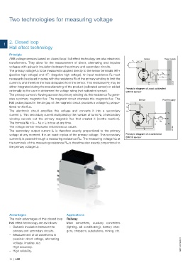
ABB voltage sensors based on closed loop Hall effect technology are also electronic Sensor Power supply
R E I P
transformers. They allow for the measurement of direct, alternating and impulse HT+
U P
voltages with galvanic insulation between the primary and secondary circuits.
HT- +
The primary voltage U P to be measured is applied directly to the sensor terminals: HT+ + V A
(positive high voltage) and HT– (negative high voltage). An input resistance R E must N P M R M 0V
N S
V M
necessarily be placed in series with the resistance R P of the primary winding to limit the _ _ V A
current I P and therefore the heat dissipated from the sensor. This resistance R E may be G0214DG
I S
either integrated during the manufacturing of the product (calibrated sensor) or added
Principle diagram of a not calibrated
externally by the user to determine the voltage rating (not calibrated sensor). EM010 sensor
The primary current I P flowing across the primary winding via this resistance R E gener-
ates a primary magnetic flux. The magnetic circuit channels this magnetic flux. The Sensor Power supply
Hall probe placed in the air gap of the magnetic circuit provides a voltage V H propor- HT+ I P
tional to this flux. U P R E
The electronic circuit amplifies this voltage and converts it into a secondary HT- +
+ V A
current I S. This secondary current multiplied by the number of turns N S of secondary
R M
N P M
winding cancels out the primary magnetic flux that created it (contra reaction). 0V
N S
V M
The formula N P x I P = N S x I S is true at any time. _ V A
_
The voltage sensor measures instantaneous values. G0213DG
I S
The secondary output current I S is therefore exactly proportional to the primary
voltage at any moment. It is an exact replica of the primary voltage. This secondary Principle diagram of a calibrated
EM010 sensor
current I S is passed through a measuring resistance R M. The measuring voltage V M at
the terminals of this measuring resistance R M is therefore also exactly proportional to
the primary voltage U P .
Advantages Applications
The main advantages of this closed loop Railway
Hall effect technology are as follows: Main converters, auxiliary converters
– Galvanic insulation between the (lighting, air conditioning), battery char-
primary and secondary circuits. gers, choppers, substations, mining, etc.
– Measurement of all waveforms is
possible: direct voltage, alternating
voltage, impulse, etc. 1SBC140076S0201
– High accuracy.
– High reliability.
10 | ABB