
Page 181 - Motor_protection_and_control_Manual_motor_starters_ contactors
P. 181
NS and NSL contactor relays
Technical data
Magnet system characteristics for NS contactor relays
Contactor relay types AC operated NS
Coil operating limits AC supply
acc. to IEC 60947-5-1 0.85...1.1 x Uc (at θ ≤ 60 °C); Uc (at θ ≤ 70 °C)
AC control voltage Rated control circuit voltage Uc at 50 Hz 24...415 V
at 60 Hz 24...415 V
Coil consumption Average pull-in value 50 Hz 33 VA
60 Hz 33 VA
50/60 Hz 33 VA
Average holding value 50 Hz 6.5 VA / 1.5 W
60 Hz 5 VA / 1.2 W
50/60 Hz 6.5 VA / 1.5 W 4
Drop-out voltage Approx. 30...50 % of Uc
Operating time
Between coil energization and: N.O. contact closing 9...24 ms
N.C. contact opening 6...18 ms
Between coil de-energization and: N.O. contact opening (1) 5...19 ms
N.C. contact closing (1) 7...22 ms
(1) The use of RC5-1 surge suppressor increases opening time by a factor of 2 to 3.
Magnet system characteristics for NSL contactor relays
Contactor relay types DC operated NSL
Coil operating limits DC supply
acc. to IEC 60947-5-1 0.85...1.1 x Uc (at θ ≤ 60 °C); Uc (at θ ≤ 70 °C)
DC control voltage Rated control circuit voltage Uc 12...240 V DC
Coil consumption Average pull-in value 3 W
Average holding value 3 W
Drop-out voltage Approx. 10...40 % of Uc
Coil time constant Open L/R 12 ms
Closed L/R 40 ms
Operating time
Between coil energization and: N.O. contact closing 36...59 ms
N.C. contact opening 31...53 ms
Between coil de-energization and: N.O. contact opening (1) 13...17 ms
N.C. contact closing (1) 15...20 ms
(1) The use of RT5 surge suppressor increases opening time by a factor of 1.1 to 1.2.
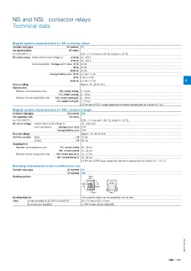
Mounting characteristics and conditions for use
Contactor relay types AC operated NS
DC operated NSL
Mounting positions Pos. 2
Pos. 4
Pos. 3
Pos. 1 Pos. 5
Mounting distances The contactor relays can be assembled side by side.
Fixing On rail according to IEC 60715, EN 60715 35 x 7.5 mm or 35 x 15 mm
By screws (not supplied) 2 x M4 screws placed diagonally
1SBC101502S0201
ABB | 4/61