
Page 482 - Motor_protection_and_control_Manual_motor_starters_ contactors
P. 482
Contactors for capacitor switching
AC-6b utilization category according to IEC 60947-4-1
Capacitor transient conditions
In Low Voltage industrial installations, capacitors are mainly used for reactive energy correction (raising the power factor). When these capacitors
are energized, overcurrents of high amplitude and high frequencies (3 to 15 kHz) occur during the transient period (1 to 2 ms).
The amplitude of these current peaks, also known as "inrush current peaks", depends on the following factors:
– The network inductances.
– The transformer power and short-circuit voltage.
– The type of power factor correction.
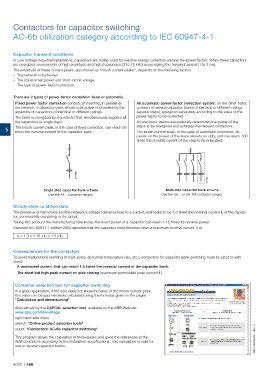
There are 2 types of power factor correction: fixed or automatic.
Fixed power factor correction consists of inserting, in parallel on An automatic power factor correction system, on the other hand,
the network, a capacitor bank whose total power is provided by the consists of several capacitor banks of identical or different ratings
assembly of capacitors of identical or different ratings. (several steps), energized separately according to the value of the
The bank is energized by a contactor that simultaneously supplies all power factor to be corrected.
the capacitors (a single step). An electronic device automatically determines the power of the
5 The inrush current peak, in the case of fixed correction, can reach 30 steps to be energized and activates the relevant contactors.
The inrush current peak, in the case of automatic correction, de-
times the nominal current of the capacitor bank.
pends on the power of the steps already on duty, and can reach 100
times the nominal current of the step to be energized.
E1178D
E1179D
Single-step capacitor bank scheme Multi-step capacitor bank scheme
Use the AF... contactor ranges. Use the UA... or UA..RA contactor ranges.
Steady state condition data
The presence of harmonics and the network's voltage tolerance lead to a current, estimated to be 1.3 times the nominal current I n of the capaci-
tor, permanently circulating in the circuit.
Taking into account the manufacturing tolerances, the exact power of a capacitor can reach 1.15 times its nominal power.
Standard IEC 60831-1 Edition 2002 specifies that the capacitor must therefore have a maximum thermal current I T of:
I T = 1.3 x 1.15 x I n = 1.5 x I n
Consequences for the contactors
To avoid malfunctions (welding of main poles, abnormal temperature rise, etc.), contactors for capacitor bank switching must be sized to with-
stand:
– A permanent current that can reach 1.5 times the nominal current of the capacitor bank.
– The short but high peak current on pole closing (maximum permissible peak current Î ).
Contactor selection tool for capacitor switching
In a given application, if the user does not know the value of the inrush current peak,
this value can be approximately calculated using the formulas given on the pages
"Calculation and dimensioning".
Alternatively by the CAPCAL selection tool, available on the ABB Website:
www.abb.com/lowvoltage
right hand side menu
search: "Online product selection tools"
select: "Contactors: AC-6b capacitor switching"
This program allows the calculation of these peaks and gives the references of the
ABB contactors according to the installation specifications. This calculation is valid for 1SBC101603S0201 - Rev. A
one or several capacitor banks.
5/282 | ABB