
Page 759 - Motor protection and control Manual motor starters, contactors and overload relays
P. 759
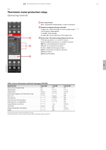
ABB  MOTOR PROTECTION AND CONTROL                                                 7/3

          —

          Thermistor motor protection relays
          Operating controls


                                             1  Test / Reset button

                                               Reset - only possible if measured value < switch-on resistance
                                             2  Indication of operational states with LEDs

                                                 U: green LED - Status indication of control supply voltage V
                                               Control supply voltage applied
                                               F: red LED - Fault message
                                               R: yellow LED - Status indication of the output relay
                                  1          3  Marker label / DIP switches (depending on device) e.g.

                                               i Single evaluation 2 x 1 c/o (SPDT) contact
                                               j Accumulative evaluation 1 x 2 c/o (SPDT) contacts
                                               y Short-circuit detection de-activated
                                  2            x Short-circuit detection activated
                                               f Non-volatile fault storage activated
                                               e Non-volatile fault storage de-activated
                                                Reset  Remote Reset
                                               Remote
                                               Test/Reset  Remote Test/Reset
                                               Remote
                                  3


        2CDC 253 001 F0015                                                                                            07


          LEDs, status information and fault messages CM-MSS
          Operational state                    U: green LED  F: red LED  R: yellow LED
          Absence of control supply voltage    OFF          OFF          OFF
          Internal fault (2)                   OFF          W            W
          Internal fault (2)                   X            X            X
          Control supply voltage not within the tolerance range  X  V    OFF
          Short circuit                        V            Y            OFF
          Interrupted wire                     V            Z            OFF
          Measuring circuit 2: Overtemperature  V           W            OFF
          Measuring circuit 1: Overtemperature  V           V            OFF
          Fault rectified but not confirmed    V            -- (1)       X
          Test function                        X            OFF          OFF
          Change of configuration not confirmed   V         OFF          X
          No fault                             V            OFF          V
          (1) Depending on the fault with the highest priority
          (2) Restart the device. If after restart the same fault is indicated, replace the device.