
Page 132 - 1SBC104119C0202_MainCatalog_R contactors
P. 132
R mechanically latched contactors
Contactors and couplers
Wiring diagrams
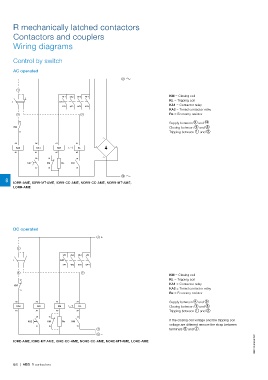
Control by switch
AC operated
9
1 1/L1 3/L2 5/L3 7/L4 KM = Closing coil
KA1 4/T2 6/T3 8/T4 KL = Tripping coil
I KA1 = Contactor relay
2/T1 KA2 = Timed contactor relay
3 Re = Economy resistor
12 2
Supply between 9 and 10
KM Closing between 1 and 3
11 Tripping between 1 and 2
A2 A2 A1 A1 + –
KA2 KA1 KM KL
A1 A1 A2 A2
KA2 58 15 14
57 KM Re KM
16 13
10
8 IORR-AME, IORR-MT-AME, IORR-CC-AME, NORR-CC-AME, NORR-MT-AME,
LORR-AME
DC operated 4+
1 1/L1 3/L2 5/L3 7/L4
KA1 4/T2 6/T3 8/T4
I
2/T1
3
12 2 KM = Closing coil
KL = Tripping coil
KM KA1 = Contactor relay
11 KA2 = Timed contactor relay
Re = Economy resistor
A2 A2 A1 A1
KA2 KA1 KM KL Supply between 4 and 5
Closing between 1 and 3
A1 A1 A2 A2 Tripping between 1 and 2
KA2 58 15 14 If the closing coil voltage and the tripping coil
57 KM Re KM voltage are different remove the strap between
terminals 5 and 7 .
16 13
7 1SBC104049S0201
5–
IORE-AME, IORE-MT-AME, IORE-CC-AME, NORE-CC-AME, NORE-MT-AME, LORE-AME
8/6 | ABB R contactors