
Page 134 - 1SBC104119C0202_MainCatalog_R contactors
P. 134
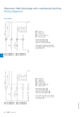
Alternator field discharge with mechanical latching
Wiring diagrams

DC operated                                      4+

      1

      3                     1/L1 3/L2 5/L3 7/L4         KM = Closing coil
                        KA1                             KL1 = Tripping coil
  12                                                    KA1 = Contactor relay
KM                          2/T1 4/T2 6/T3 8/T4         KA2 = Timed contactor relay
                                                        RE = Economy resistor
  11           A1       A1        2
                KA1       KM                            Supply between 4 and 5
  Y1 A1                       A1                        Closing between 1 and 3
     KA2       A2       A2     KL1                      Tripping KL1 between 1 and 2

     A2                       A2                        If the closing coil voltage and the tripping
                                                        coil voltage are different, remove the strap
          KA2  15      15     14                        between 5 and 7 .
               18    KM RE    13

                       16

                                                 7

                                                 5–

       AM-CC-JORE550-21 ... AM-CC-JORE2100-21

8 AM-CC-JORE550-31 ... AM-CC-JORE2100-31

                                                 4+

1

      3                     1/L1 3/L2 5/L3 7/L4         KM = Closing coil
                        KA1                             KL1 = Tripping coil
  12                                                    KL2 = Tripping coil
KM                          2/T1 4/T2 6/T3 8/T4         KA1 = Contactor relay
                                                        KA2 = Timed contactor relay
  11           A1       A1        2                  8  RE = Economy resistor
                KA1       KM
  Y1 A1                       A1                 A1     Supply between 4 and 5
     KA2       A2       A2     KL1                KL2   Closing between 1 and 3
                                                        Tripping KL1 between 1 and 2
     A2                       A2                 A2     Tripping KL2 between 8 and 9

          KA2  15      15     14 104                    If the closing coil voltage and the tripping
               18    KM RE    13 103                    coil voltage are different, remove the strap
                                                        between 5 and 7 .
                       16

                                                 9
                                                 7

                                                 5–

AMF-CC-JORE550-21 ... AMF-CC-JORE2100-21                                                              1SBC104096S0201
AMF-CC-JORE550-31 ... AMF-CC-JORE2100-31

8/8 | ABB R contactors