
Page 57 - Catalog Softstarters PSR PSE PSTX
P. 57
PSTX – The advanced range
Circuit diagrams
PSTX30...370
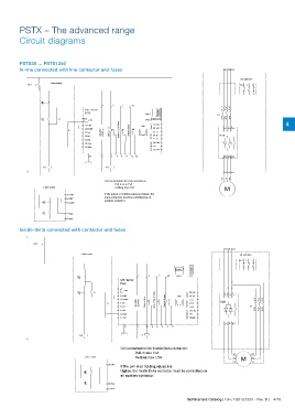
PSTX30 ... PSTX1250
In Line with main contactor closed only during operation.
In-line connected with line contactor and fuses 1L1 3L2 5L3
Alt. with fuses
2-wire control
O/I F1.1 .2 .3
O E
1 4 7 10
Soft starter 1/L1 3/L2 5/L3
PSTX Com 1 Anybus K1
I E K7 21 + 24V Com 2 2/T1 4/T2 6/T3
20
19 GND HMI 23 +(B) 4
18 DGND K6 Com 3 24 -(A) 1L1 3L2 5L3
K7 K4 Default:Top of ramp K5 Default: Event
17 In2 100-250V 50/60 Hz Default: Run 25 T1
16 In1 Temp In 26 T2 PSTX
15 In0 27 T3
Analog out 29 +
14 Stop 28 +24V
13 Start 30 GND
22 2 5 6 8 9 11 12 2T1 4T2 6T3
K7 K1
2T1 4T2 6T3
U1 V1 W1
Coil consumption for main contactors.
Pull-in max 15A
3-wire control Holding max 1.5A M
20 +24V If the pull-in or holding values are higher, the
main contactors must be controlled via an
19 GND auxiliary contactor.
O E 18 DGND
I E 14 Stop
13 Start
Inside-delta connected with contactor and fuses Björn Johansson Approved RE Application diagram
Lars Eriksson 150817 A
1SFB536005G5006
ABB ABB AB, Control Products
4/18 1SFC132012C0201 - Rev. B | Softstarters Catalog Softstarters Catalog | 1SFC132012C0201 - Rev. B | 4/19