
Page 119 - EPR Catalog 2015
P. 119
Grid feeding monitoring relays -
Voltage and frequency monitoring functions
Applications
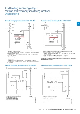
Example of single-phase application CM-UFD.M22 Example of three-phase application CM-UFD.M22
9 9
LN LN LN L1 L2 L3 N 2
1 8
230 V AC
1
L1 N
7
2CDC 252 004 F0014 230 V AC
2CDC 252 003 F0014L1 N
CP-E 24/X CP-E 24/X 11
11 L+ L-
L+ L- 24 V DC
L+IN L-IN
24 V DC
CP-B 24/X 12
L+IN L-IN
L+OUTL-OUT
CP-B 24/X 12
24 V DC
L+OUTL-OUT
13
24 V DC
13 7
10
A1 A2 Y1 Y2 Y3 Y0 L1 L2 L3 N 10
A1 A2 Y1 Y2 Y3 Y0 L1 L2 L3 N
ESC CM-UFD
OK
ESC CM-UFD
OK
U/T U/T
F F
14 11 12 24 21 22 34 31 32 4 14 11 12 24 21 22 34 31 32
18 15 16 28 25 26 38 35 36 18 15 16 28 25 26 38 35 36
2
3 4
6 2
G5 3
6
G
1. Main circuit breaker DG or DGL 9. Control supply voltage for CM-UFD.M22 (SPI) and tripping device (DDI)*
2. DDI: Automatic circuit breaker or contactor equipped with low voltage coil and 10. Device protection fuse for the CM-UFD.M22
11. Primary switch mode power supply unit CP-E (230 V AC / 24 V DC) for the buf-
motor for automatic closure
3. Auxiliary contact of DDI, necessary for realizing the feedback function (compul- fer module CP-B*
12. Ultra-capacitor based buffer module CP-B (24 V DC in/out)
sory for CM-UFD.M22) 13. Wire protection fuse for the output of the buffer module CP-B
4. DDI short-circuit protection
5. Generator and/or inverter * In accordance to CEI 0-21 regulation, in case of loss of control supply voltage it’s asked to guarantee, at least for 5 seconds, the functionality
6. Generator (DDG) of the CM-UFD.M22, the operability of the DDI and when present the command coil for operating the redundancy device. This function has to
7. Protection fuse for the measuring circuit of the CM-UFD.M22 (optional) be realized by external buffer or UPS devices.
8. Shunt trip coil for feedback function (P>20 kW). This coil can control DG/DGL or
Example of three-phase application - CM-UFD.M31
DDG devices
L1
Example of single-phase application - CM-UFD.M31 L2
L3
L1 N Public grid
N Public grid
where applicable,
where applicable, a transformer
a transformer
ͨ6 A ͨ10 A ͨ10 A ͨ10 A ͨ6 A
A1 A2 1115 2125
3135 L1 L2 L3 N
A1 A2 1115 2125 3135 L1 L2 L3 N
1216 1418 2226 2428 3236 3438 ቤባቢ ቤባቢ
Y3 Y2 Y1 Y0 Y3 Y2 Y1 Y0
1216 1418 2226 2428 3236 3438
K1 ቢብ K1 ቢ ብ
K2 ባቦ K2 ባ ቦ
ቢ Control input 1, feedback loop for switching device 1 Inverter(s) ቢ Control input 1, feedback loop for switching device 1
ባ Control input 2, feedback loop for switching device 2 Generator(s) ባ Control input 2, feedback loop for switching device 2
ቤ Control input 3 (e.g. for remote trip) ቤ Control input 3 (e.g. for remote trip)
ብ Switching device 1 of the section switch ብ Switching device 1 of the section switch
ቦ Switching device 2 of the section switch ቦ Switching device 2 of the section switch
2CDC 252 006 F0213 Inverter(s)
2CDC 252 007 F0213Generator(s)
2CDC 110 004 C0210 | Catalog Electronic Products and Relays 2015 | ABB 2/52