
Page 144 - EPR Catalog 2015
P. 144
Motor load monitoring relays
Technical information
The CM-LWN module monitors the load status of inductive loads.
The primary application is the monitoring of single- or three-phase asynchronous motors (squirrel cage) under varying load
conditions. The measuring principle is based on the evaluation of the phase shift (M) between the voltage and the current in one
phase.
2 The phase difference is nearly inversely proportional to the load. Therefore, cos M, measured relatively from 0 to 1, measures
the relationship of effective power to apparent power. A value towards 0 indicates low load and a value towards 1 indicates
high load.
Threshold values can be set individually for cos Mmax and cos Mmin If the set threshold value is reached, a LED lights up and the
relay is de-energized.
If cos M returns to the acceptable limits (taking into account the hysteresis), the relay is reset to its original state and the LED
flashes permanently to indicate the occurrence of the trip event. This message can be deleted using the reset button or by
switching off the supply.
A time delay (Time S) of 0.3 to 30 s can be set for the starting phase of the motor. It is also possible to set a response delay
time (Time R) of 0.2 to 2 s to suppress unwanted tripping due to unavoidable short load changes during normal operation.
To guarantee correct operation of the response delay (Time R), the adjusted value for cos Mmax has to be higher than the value
for cos Mmin plus the hysteresis. Consequently, the overload and underload indication must not be active at the same time.
Due to the internal electrical isolation of the supply circuit and the measuring circuit, it is also possible to use the device in sys-
tems with different supply voltages.
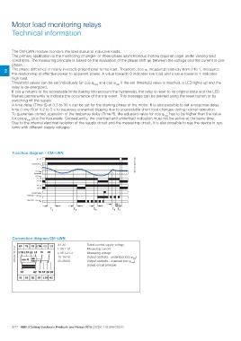
Function diagram - CM-LWN 2CDC 252 105 F0004TRTR TR TS
1SVC 110 000 F0130
A1-A2
Current in L1
con Mmax
hysteresis
con Mmin
15-18
15-16
25-28
25-26
Reset button
Red LED - cos Mmin
Red LED - cos Mmax
TS
Connection diagram CM-LWN Rated control supply voltage
A1-A2 Measuring current
L1/K-L1/L
L1/K-L2-L3 Measuring voltage
15-16/18 Output contacts - underload (cos Mmin)
25-26/28 Output contacts - overload (cos Mmax)
closed-circuit principle
2/77 ABB | Catalog Electronic Products and Relays 2015 | 2CDC 110 004 C0210