
Page 145 - EPR Catalog 2015
P. 145
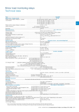
Motor load monitoring relays
Technical data

Type                                                                                                                   CM-LWN              2
Input circuit - Supply circuit                                                                                            A1-A2
Rated control supply voltage Us - power
consumption                                                    A1-A2 24-240 V AC/DC approx. 8.4 VA/W
                                                               A1-A2 110-130 V AC approx. 3.6 VA
Rated control supply voltage Us tolerance                      A1-A2 220-240 V AC approx. 3.6 VA
Rated frequency                                                A1-A2 380-440 V AC approx. 3.6 VA
                                                               A1-A2 480-500 V AC approx. 3.6 VA
Duty time
Measuring circuit                                                         -15 %...+10 %
Monitoring function
                                                       AC versions 50-60 Hz
                                                  AC/DC versions 15-400 Hz or DC

                                                                          100 %

                                                                                                                  L1/L-L1/K-L2-L3
                                                                          Motor load monitoring by cos M

Voltage range                                               L1/K-L2-L3 110-500 V AC single-phase or three-phase
Current range                                                 L1/L-L1/K 0.5-5 A version 2-20 A version
Permissible overload of current input                                        25 A for 3 s 100 A for 3 s
Thresholds                                                                   cos Mmin and cos Mmax adjustable from 0 to 1

Hysteresis (related to phase angle M in °)                                   4°

Frequency of measuring voltage                                            15-400 Hz

Response time                                                             300 ms
                                                                                               indication of over- and undervoltage fault
Timing circuits
Start-up time (Time S)                                                    0.3-30 s, adjustable
Response delay (Time R)                                                   0.2-2 s, adjustable
Accuracy within the rated control supply voltage tolerance                ͬt ͨ 0.5 %
Accuracy within the temperature range                                     ͬt ͨ 0.06 % / °C

Indication of operational states                                          U: green LED
Control supply voltage                                                    cos Mmin: red LED
below cos Mmin
                                                                          cos Mmax: red LED
cos Mmax exceeded

Output circuits                                                                                         15-16/18, 25-26/28

Kind of output                                                            2 x 1 c/o contact
Operational principle                                                     closed-circuit principle 1)
Contact material                                                          AgCdO

Rated voltage (VDE 0110, IEC 664-1, IEC 947-1)                            250 V

Max. switching voltage                                                    400 V AC, 300 V DC

Rated operational current Ie (IEC/EN 60947-1)      AC-12 (resistive) 230 V 4 A
                                                  AC-15 (inductive) 230 V 3 A

                                                  DC-12 (resistive) 24 V 4 A

                                                  DC-13 (inductive) 24 V 2 A

AC rating (UL 508)       Utilization category (Control Circuit Rating Code) B 300

                                            max. rated operational voltage 300 V AC

                                   max. continuous thermal current at B 300 5 A

                         max. making/breaking apparent power at B 300 3600/360 VA

Mechanical lifetime                                                       30 x 106 switching cycles

Electrical lifetime                               at AC-12, 230 V, 4 A 0.1 x 10⁶ switching cycles

Max. fuse rating to achieve short-circuit         n/c / n/o contact 10 A fast-acting / 10 A fast-acting

protection

General data

Dimensions (W x H x D)                                                    45 mm x 78 mm x 100 mm (1.77 inch x 3.07 inch x 3.94 inch)
Mounting position                                                         any

Degree of protection                              housing / terminals IP50 / IP20
Ambient temperature range                         operation / storage -25...+65 °C / -40...+85 °C
Mounting
                                                                               DIN rail (IEC/EN 60715)

Electrical connection                       fine-strand with wire end ferrule 2 x 2.5 mm2 (2 x 14 AWG)
Wire size

Standards                                                                 IEC 255-6, EN 60255-6
Product standard                                                          2006/95/EC
Low Voltage Directive                                                     2004/108/EC, 91/263/EEC, 92/31/EEC, 93/68/EEC, 93/67/EEC
EMC Directive

Electromagnetic compatibility                                                                 EN 61000-6-2, EN 61000-6-4

electrostatic discharge                           IEC/EN 61000-4-2 Level 3 (6 kV / 8 kV)

radiated, radio-frequency, electromagnetic field  IEC/EN 61000-4-3 Level 3 (10 V/m)

electrical fast transient / burst                 IEC/EN 61000-4-4 Level 3 (2 kV / 5 kHz)

surge                                             IEC/EN 61000-4-5 Level 4 (2 kV L-L)

conducted disturbances, induced by radio-frequency fields IEC/EN 61000-4-6 Level 3 (10 V)

Operational reliability (IEC 68-2-6)                                      5g

Mechanical resistance (IEC 68-2-6)                                        10 g

Environmental testing (IEC 68-2-30)                                       24 h cycle time, 55 °C, 93 % rel., 96 h

Isolation data                                                            250 V, 400 V, 500 V depending on the version
Rating (HD 625.1 S1, VDE 0110, IEC 664-1, IEC 60255-5)                    4 kV / 1.2 - 50 μs
Rated insulation voltage between supply- , measuring- and output circuit  2,5 kV, 50 Hz, 1 min.
Rated impulse withstand voltage between all isolated circuits             3
Test voltage between all isolated circuits                                III
Pollution category
Overvoltage category

1) Open-circuit principle: Output relay is energized if the measured value exceeds/drops below the adjusted threshold.
  Closed-circuit principle: Output relay is de-energized if the measured value exceeds/drops below the adjusted threshold.

                                                            2CDC 110 004 C0210 | Catalog Electronic Products and Relays 2015 | ABB 2/78