
Page 190 - PLC Automation
P. 190
188 MAIN CATALOG PLC AUTOMATION
—
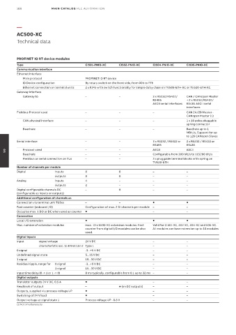
AC500-XC
Technical data
PROFINET IO RT device modules
Type CI501-PNIO-XC CI502-PNIO-XC CI504-PNIO-XC CI506-PNIO-XC
Communication interface
Ethernet Interface
Main protocol PROFINET IO RT device
ID Device configuration By rotary switch on the front side, from 00h to FFh
Ethernet connection on terminal units 2 x RJ45 with switch functionality for simple daisy chain on TU508-ETH-XC or TU520-ETH-XC
Gateway Interface
Gateway to – – 3 x RS232/RS422/ CAN / CANopen Master
RS485 + 2 x RS232/RS422/
ASCII serial interfaces RS485 ASCII serial
interfaces
Fieldbus Protocol used – – – CAN 2A/2B Master -
CANopen Master (1)
CAN physical interface – – – 1 x 10 poles pluggable
spring connector
Baudrate – – – Baudrate up to 1
MBit/s, Support for up
to 126 CANopen Slaves
Serial interface – – 3 x RS232 / RS422 or 2 x RS232 / RS422 or
RS485 RS485
Protocol used – – ASCII ASCII
Baudrate – – Configurable from 300 bit/s to 115200 bit/s
05
Fieldbus or serial connection on TUs – – 3 x pluggable terminal blocks with spring on
TU520-ETH
Number of channels per module
Digital inputs 8 8 – –
outputs 8 8 – –
Analog inputs 4 – – –
outputs 2 – – –
Digital configurable channels DC – 8 – –
(configurable as inputs or outputs)
Additional configuration of channels as
Connection via terminal unit TU5xx – –
Fast counter (onboard I/O) Configuration of max. 2 DI channels per module – –
Occupies max. 1 DO or DC when used as counter – –
Connection
Local I/O extension
Max. number of extension modules max. 10 x S500-XC extension modules. Fast Valid for CI501-XC, 502-XC, 504-XC and 506-XC.
counter from digital I/O modules can be also All modules can have extension up to 10 modules
used.
Digital inputs
Input signal voltage 24 V DC – –
characteristic acc. to EN 61132-2 Type 1 – –
0 signal -3...+5 V DC – –
Undefined signal state 5...15 V DC – –
1 signal 15...30 V DC – –
Residual ripple, range for 0 signal -3...+5 V DC – –
1 signal 15...30 V DC – –
Input time delay (0 -> 1 or 1 -> 0) 8 ms typically, configurable from 0.1 up to 32 ms – –
Digital outputs
Transistor outputs 24 V DC, 0.5 A – –
Readback of output – (on DC outputs) – –
Outputs, supplied via process voltage UP – –
Switching of 24 V load – –
Output voltage at signal state 1 Process voltage UP - 0.8 V – –
(1) Not simultaneously.