Page 1096 - Controle-industriel
P. 1096

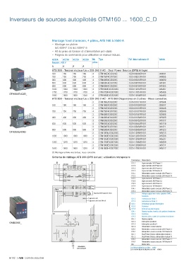
Inverseurs de sources autopilotés OTM160 ... 1600_C_D


                                  Montage fond d'armoire, 4 pôles, ATS 160 à 2500 A
                                     – Montage sur platine
                                     – IEC 60947-3 & IEC 60947-6
                                     – Kit de prise de tension et d'alimentation pré-câblé
                                     – Poignée de commande pour utilisation en manuel incluse.
                                  AC20A  AC21A  AC22A  AC23A  Nb  Type            Réf. Internationale @  Article
                                  Tension = 400 V          pôles
                                  A      A     A     A
                                  ATS 300 - Tension moteur Ue = 220-240 V AC - Dual Power Source (DPS) intégré
                                  160    160   160   160   4   OTM160E4C3D230C    1SCA106305R1001    940091
                                  250    250   250   250   4   OTM250E4C3D230C    1SCA106313R1001    940085
                                  400    400   400   400   4   OTM400E4C3D230C    1SCA106318R1001    940090
                                  630    630   630   630   4   OTM630E4C3D230C    1SCA108726R1001    941961
                                  800    800   800   800   4   OTM800E4C3D230C    1SCA108728R1001    941965
                                  1000   1000  1000  1000  4   OTM1000E4C3D230C   1SCA112852R1001    945497
                                  1250   1250  1250  1250  4   OTM1250E4C3D230C   1SCA112851R1001    945496
       OTM250E4C3D_               1600   1600  1600  1250  4   OTM1600E4C3D230C   1SCA112848R1001    945493
                                  ATS 800 - Tension moteur Ue = 220-240 V AC - ATS 800 Disponibles en 3 pôles - Nous consulter.
                                                           3   OTM160E3C8D230C    1SCA101017R1001    935944
                                  160    160   160   160   4   OTM160E4C8D230C    1SCA101020R1001    935947
                                                           3   OTM250E3C8D230C    1SCA101019R1001    935946
                                  250    250   250   250   4   OTM250E4C8D230C    1SCA101022R1001    935949
                                                           3   OTM400E3C8D230C    1SCA101061R1001    935986
                                  400    400   400   400   4   OTM400E4C8D230C    1SCA101064R1001    935989
                                                           3   OTM630E3C8D230C    1SCA108452R1001    941817
                                  630    630   630   630   4   OTM630E4C8D230C    1SCA108453R1001    941819
                                                           3   OTM800E3C8D230C    1SCA108454R1001    941821
                                  800    800   800   800   4   OTM800E4C8D230C    1SCA108455R1001    941823
       OTM250E4C8D_                                        3   OTM1000E3C8D230C   1SCA112868R1001    945513
                                  1000   1000  1000  1000  4   OTM1000E4C8D230C   1SCA112861R1001    945506
                                                           3   OTM1250E3C8D230C   1SCA112862R1001    945507
                                  1250   1250  1250  1250  4   OTM1250E4C8D230C   1SCA112864R1001    945509
                                                           3   OTM1600E3C8D230C   1SCA112866R1001    945511
                                  1600   1600  1600  1250  4   OTM1600E4C8D230C   1SCA112867R1001    945512
                                  (1) Montage arrivée vers le bas, nous consulter.
                                  Schéma de câblage ATS 300 (DPS inclus) : utilisation tétrapolaire
                                                                                    Connecteur Description
                                                                                    X11:1  Ligne normale LN1:Phase L1
                                         ATS 300
                                                                                    X11:2  Ligne normale LN1:Phase L2
                                                                                    X11:3  Ligne normale LN1:Phase L3
                                                                                    X11:4  Ligne normale LN1:Neutre N
                                                                                    X13.1  Alimentation source normale LN1:Phase L1
                                                                                    X13.2  Alimentation source normale LN1:Neutre N
                                           Equipment  Equipment
                                                                                    X12:1  Ligne secours LN2:Phase L1
                                           Power  Power
                                                                                    X12:2  Ligne secours LN2:Phase L2
                                                                                    X12:3  Ligne secours LN2:Phase L3
                                                        Start/Stop }                X12:4  Ligne secours LN2:Neutre N
                                                        COM
                                    Alarm               Start/Stop                  X14:1  Alimentation source secours LN2:Phase L1
                                    / Man in put        OK                          X14:2  Alimentation source secours LN2:Neutre N
                                                        Alarm } Signaling OK/Equipment Alarm  X21:1  Voltage supply from motor operator OME_
                                                        COM
                                                Supply                                    Commun
                                                         Equipment earth            X21:2  Fermeture de l'inter. I
                                                         Equipment earth from DIN-rail  X21:3  Fermeture de l'inter. II
                                                                                          Démarrage groupe électrogène
                                                                                    X23:2  Commun
                                                                                    X23:3  Arrêt groupe électrogène
                                                                                    X24.1  Alarme inactive, fermée si le système fonctionne
                                                                                    X23:1 }
                                                                                    X24.2  Commun
                                                                                    X24.3  Alarme active, ouvert si le système fonctionne
                                                                                    X31.1  Alarme poignée
                                                                                    X31.2  Interrupteur position I
       OMD300E_
                                                                                    X31.3  Interrupteur position II
                                                                                    X31.4  Alimentation contact alarme
                                                                                    X26.1  Alimentation source normale LN1:Phase L1
                                                                                    X26.2  Alimentation source normale LN1:Neutre N
                                                                                    X27.1  Dual Power Source: alimentation moteur L
                                                                                    X27.2  Dual Power Source: alimentation moteur N
                                                                                    X28.1  Alimentation source secours LN2:Phase L1
                                                                                    X28.2  Alimentation source secours LN2:Neutre N
                                                                                    X61   Borne terre
                                                  Alimentation
                                                 moteur intégrée                   Les fiches indiquées en bleu = sortie
                                                                                   Les connectiques indiquées en noir = entrée
       6/102  |  ABB  Contrôle industriel
   1091   1092   1093   1094   1095   1096   1097   1098   1099   1100   1101