Page 323 - Railways Applications Terminal blocks
P. 323

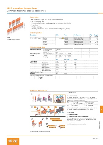
JB10 screwless jumper bars
         Common terminal block accessories


                                    Description
                                    Facilitate & secure your jumper bar assembly process:
                                       – Screwless mounting,
                                       – Pre-cut poles for alternated jumpering between terminal blocks,
                              1SNK160146F0014    – Insulated,
                                       – Positive locking,
                                       – Perfectly adapted to low level electrical contact (20mA, 50mV).

                                    Ordering details
                                    Description                   Color     Type      Part Number        Pkg  Weight
                                                                                                         qty  (1 pce) g
         JB10
                                    10 mm 0.394 in spacing  2 poles  Orange  JB10-2   1SNK910302R0000    50     4.60
         10 mm 0.394 in spacing                    3 poles                  JB10-3    1SNK910303R0000    50     7.10
                                                   4 poles                  JB10-4    1SNK910304R0000    40     9.40
                                                   5 poles                  JB10-5    1SNK910305R0000    30    12.00
                                                   10 poles                 JB10-10   1SNK910310R0000    20    24.00
                                    Main technical data
                                    Material specifications  Insulating material  Polyamide
                                                   Flammability   V0
                                                   NF F 16 101    I2F3
                                    Ambient temperature  Service IEC 60068-2-1  -55 ... +110 °C  -67 ... +230 °F
                                    min/max        Storage        -55 ... +110 °C  -67 ... +230 °F
                                                   Installing     -5 ... +40 °C  +23 ... +104 °F
                                                                  IEC       UL - CSA   Ex e
                                    Rated current                 76 A      67 A
                                    Rated voltage  1 - Standard use  1000 V  600 V     693 V
                                                2 - Cut extremities  800 V  300 V      440 V
                                                3 - Cut poles     630 V     300 V      440 V
                                                4 -  Alternated poles  400 V  150 V    275 V
                                                5 -  Alternated poles   250 V  150 V   176 V
                                                  with cut extremities
                                    Impulse withstand voltage     6000 V
                                    Protection                    IP20      NEMA 1
                                    All the main technical data are indicative “manufacturer” values.

                                               RoHS


                                    Mounting instructions
                                                                              1 - Standard use
                                                                              2 - Cut extremities
                                                                              For voltage rating > 50 V and Uimp > 2.5 KV, the below
                                                                              accessories must be installed on the cut side of the jumper
                                                                              to guarantee IP20 and voltage rating:
                                                                              ZS...  Feed-through   CS circuit separator
                                                                                    Double deck / triple deck  ES… end section
                                                                              ZK…   All functions   EK… end section
                                                                              Ensure a good straight cut by positioning the cutting tool on
                                                                              the vertical snicks of the insulated part of the jumper.  9
                                                                              3 - Cut poles
                                                                              4 - Alternated poles
                                                                              5 - Alternated poles with cut extremities
                                                                              When using cut jumpers, cut extremities should be placed
                                                                              oppositely to allow end sections / circuit separators place-
                                                                              ment at each cut extremities.
                                                                                                                    1SNK160031S0201
                                                                              For all other applications, please consult us.


                                    Technical data valid for copper conductors only.


                                                                                                           PAGE 321
   318   319   320   321   322   323   324   325   326   327   328