
Page 141 - Motor protection and control Manual motor starters, contactors and overload relays
P. 141
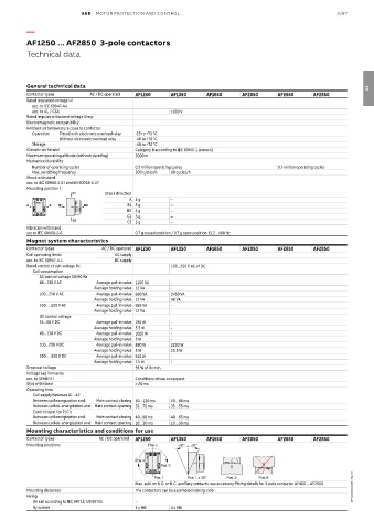
ABB  MOTOR PROTECTION AND CONTROL                                                3/67

          —

          AF1250 ... AF2850  3-pole contactors
          Technical data


          General technical data                                                                                      03
          Contactor types     AC / DC operated  AF1250  AF1350     AF1650     AF2050     AF2650      AF2850
          Rated insulation voltage Ui
           acc. to IEC 60947-4-1
           acc. to UL / CSA                            1000 V
          Rated impulse withstand voltage Uimp.
          Electromagnetic compatibility
          Ambient air temperature close to contactor
           Operation  Fitted with electronic overload relay  -25 to +70 °C
                    Without electronic overload relay  -40 to +70 °C
           Storage                          -40 to +70 °C
          Climatic withstand                Category B according to IEC 60947-1 Annex Q
          Maximum operating altitude (without derating)  3000 m
          Mechanical durability
           Number of operating cycles       0.5 million operating cycles                 0.3 million operating cycles
           Max. switching frequency         300 cycles/h  60 cycles/h
          Shock withstand
          acc. to IEC 60068-2-27 and EN 60068-2-27
          Mounting position 1
                        C1        Shock direction
                                          A 5 g        –
             ABB
          A      A  B1      B2            B1 5 g       –
                                          B2 5 g       –
                                          C1 5 g       –
                        C2               C2 5 g        –
          Vibration withstand
          acc to IEC 60068-2-6              0.7 g closed position / 0.7 g open position 13.2…100 Hz
          Magnet system characteristics
          Contactor types        AC / DC operated AF1250  AF1350   AF1650     AF2050     AF2650      AF2850
          Coil operating limits       AC supply
          acc. to IEC 60947-4-1      DC supply
          Rated control circuit voltage Uc             100...250 V AC or DC
            Coil consumption
              AC control voltage 50/60 Hz
              48...130 V AC     Average pull-in value 1100 VA  -
                               Average holding value 12 VA  -
              100...250 V AC    Average pull-in value 880 VA  2450 VA
                               Average holding value 12 VA  48 VA
              250 … 500 V AC    Average pull-in value 985 VA  -
                               Average holding value 12 VA  -
              DC control voltage
              24...60 V DC      Average pull-in value 785 W  -
                               Average holding value 5.5 W  -
              48...130 V DC     Average pull-in value 1020 W  -
                               Average holding value 5 W  -
              100...250 V DC    Average pull-in value 880 W  2290 W
                               Average holding value 5 W  20.5 W
              250 … 500 V DC    Average pull-in value 910 W  -
                               Average holding value 7.5 W  -
          Drop-out voltage                  55 % of Uc min.
          Voltage sag immunity
          acc. to SEMI F47                  Conditions of use on request
          Dips withstand                    ≥ 20 ms
          Operating time
            Coil supply between A1 - A2
            Between coil energization and:  Main contact closing 50…120 ms  50…80 ms
            Between coil de-energization and: Main contact opening 33…70 ms  35…55 ms
            Control input for PLC's
            Between coil energization and:  Main contact closing 40...90 ms  40…65 ms
            Between coil de-energization and: Main contact opening 10…30 ms  10…30 ms
          Mounting characteristics and conditions for use
          Contactor types        AC / DC operated  AF1250  AF1350  AF1650     AF2050     AF2650      AF2850
          Mounting positions                    Pos. 2    +30°  -30°

                                            Pos. 4
                                                    Pos. 3
                                                  Pos. 1     Pos. 1 ± 30°  Pos. 5  Pos. 6
                                            Max. add-on N.O. or N.C. auxiliary contacts: see accessory fitting details for 3-pole contactor AF400 ... AF2650
          Mounting distances                The contactors can be assembled side by side                         1SFC101113C0201 - Rev. E 1SFC101113C0201
          Fixing
            On rail according to IEC 60715, EN 60715  –
            By screws                       4 x M6     4 x M8