
Page 138 - Motor protection and control Manual motor starters, contactors and overload relays
P. 138
3/64 ABB MOTOR PROTECTION AND CONTROL
—
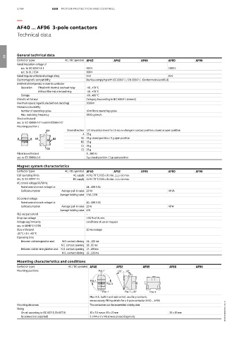
AF40 ... AF96 3-pole contactors
Technical data
General technical data
Contactor types AC / DC operated AF40 AF52 AF65 AF80 AF96
03
Rated insulation voltage Ui
acc. to IEC 60947-4-1 690 V 1000 V
acc. to UL / CSA 600 V
Rated impulse withstand voltage Uimp. 6 kV 8 kV
Electromagnetic compatibility Devices complying with IEC 60947-1 / EN 60947-1 - Environment A and B (1)
Ambient air temperature close to contactor
Operation Fitted with thermal overload relay -40...+70 °C
Without thermal overload relay -40...+70 °C
Storage -60...+80 °C
Climatic withstand Category B according to IEC 60947-1 Annex Q
Maximum operating altitude (without derating) 3000 m
Mechanical durability
Number of operating cycles 10 millions operating cycles
Max. switching frequency 3600 cycles/h
Shock withstand
acc. to IEC 60068-2-27 and EN 60068-2-27
Mounting position 1
C1 Shock direction 1/2 sinusoidal shock for 11 ms: no change in contact position, closed or open position
A 25 g
A A B1 B2 B1 25 g closed position / 5 g open position
B2 15 g
C1 25 g
C2 C2 25 g
Vibration withstand 5...300 Hz
acc. to IEC 60068-2-6 3 g closed position / 3 g open position
Magnet system characteristics
Contactor types AC / DC operated AF40 AF52 AF65 AF80 AF96
Coil operating limits AC supply At θ ≤ 70 °C 0.85 x Uc min...1.1 x Uc max.
acc. to IEC 60947-4-1 DC supply At θ ≤ 70 °C 0.85 x Uc min...1.1 x Uc max.
AC control voltage 50/60 Hz
Rated control circuit voltage Uc 24...500 V AC
Coil consumption Average pull-in value 25 VA 40 VA
Average holding value 4 VA / 2 W
DC control voltage
Rated control circuit voltage Uc 20...500 V AC
Coil consumption Average pull-in value 25 W 40 W
Average holding value 2 W
PLC-output control –
Drop-out voltage ≤ 60 % of Uc min.
Voltage sag immunity conditions of use on request
acc. to SEMI F47-0706
Dips withstand 20 ms average
-20 °C ≤ θ ≤ +60 °C
Operating time
Between coil energization and: N.O. contact closing 42...100 ms
N.C. contact opening 38...95 ms
Between coil de-energization and: N.O. contact opening 17...100 ms
N.C. contact closing 19...105 ms
Mounting characteristics and conditions
Contactor types AC / DC operated AF40 AF52 AF65 AF80 AF96
Mounting positions Pos. 2 +30° -30°
Pos. 4
Pos. 3
Pos. 1 Pos. 1 ± 30° Pos. 5
Max. N.C. built-in and add-on N.C. auxiliary contacts:
see accessory fitting details for a 3-pole contactor AF40 ... AF96
Mounting distances The contactors can be assembled side by side
Fixing
On rail according to IEC 60715, EN 60715 35 x 7.5 mm or 35 x 15 mm 35 x 15 mm 1SBC100488S0201 - Rev. D
By screws (not supplied) 2 x M4 or 2 x M6 screws placed diagonally