Page 181 - 1SBC104119C0202_MainCatalog_R contactors
P. 181

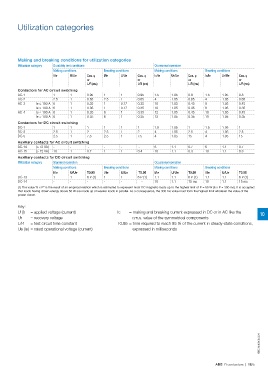
Utilization categories

Making and breaking conditions for utilization categories

Utilization category  Durability test conditions                                           Occasional operation
                                                                                           Making conditions
                      Making conditions                     Breaking conditions            Ic/Ie Ur/Ue                     Breaking conditions
                                                                                                                           Ic/Ie Ur/Ue
                      I/Ie  U/Ue                  Cos. φ    I/Ie  U/Ue           Cos. φ                          Cos. φ                         Cos. φ
                                                                                 or                              or                             or
                                                  or                             L/R (ms)                        L/R (ms)                       L/R (ms)

                                                  L/R (ms)

Contactors for AC circuit switching

AC-1                  11                          0.95      1     1 0.95 1.5                  1.05 0.8                     1.5  1.05 0.8
                                                  0.65      2.5   1 0.65 4                                                      1.05 0.65
AC-2                  2.5 1                       0.35      1     0.17 0.35 10                1.05 0.65 4                       1.05 0.45
                                                  0.35      1     0.17 0.35 10                                                  1.05 0.35
AC-3   Ie ≤ 100 A 6         1                     0.35      6     1 0.35 12                   1.05 0.45 8                       1.05 0.45
                                                  0.35      6     1 0.35 12                                                     1.05 0.35
       Ie > 100 A 6         1                                                                 1.05 0.35 8

AC-4   Ie ≤ 100 A 6         1                                                                 1.05 0.45 10

       Ie > 100 A 6         1                                                                 1.05 0.35 10

Contactors for DC circuit switching

DC-1                  11111                                                      1 1.5 1.05 1 1.5 1.05 1

DC-3                  2.5 1 2 2.5 1                                              2         4  1.05 2.5                     4    1.05 2.5

DC-5                  2.5 1                       7.5 2.5 1                      7.5 4        1.05 15                      4    1.05 15

Auxiliary contacts for AC circuit switching

AC-14  (≤ 72 VA) -          -                     --              -              - 6 1.1 0.7 6 1.1 0.7

AC-15  (> 72 VA) 10         1                     0.7 1           1              0.4 10       1.1 0.3 10                        1.1 0.3

Auxiliary contacts for DC circuit switching

Utilization category  Standard operation                                                   Occasional operation

                      Making conditions                     Breaking conditions            Making conditions               Breaking conditions

                      I/Ie  U/Ue                  T0.95     I/Ie U/Ue            T0.95     I/Ie U/Ue             T0.95     I/Ie U/Ue            T0.95
                                                            11                             1.1 1.1                         1.1 1.1
DC-13                 1 1 6 P (1)                           --                   6 P (1)   10 1.1                6 P (1)   10 1.1               6 P (1)
DC-14                 ---                                                           -                            15 ms                          15 ms

(1) The value "6 x P" is the result of an empirical relation which is estimated to represent most DC magnetic loads up to the highest limit of P = 50 W (6 x P = 300 ms). It is accepted
that loads having drawn energy above 50 W are made up of weaker loads in parallel. As a consequence, the 300 ms value must form the highest limit whatever the value of the
power drawn.

Key:

U (I) 	 = applied voltage (current)	                              Ic 	 = making and breaking current expressed in DC or in AC like the                                                                     10

Ur	 = recovery voltage 		                                                        r.m.s. value of the symmetrical components

L/R 	 = test circuit time constant	                               T0.95 	= time required to reach 95 % of the current in steady-state conditions,

Ue (Ie) 	= rated operational voltage (current)		                                 expressed in milliseconds

                                                                                                                                                                                          1SBC104080S0201

                                                                                                                                ABB R contactors | 10/5
   176   177   178   179   180   181   182   183   184   185   186