
Page 128 - EPR Catalog 2015
P. 128
Insulation monitoring relays for unearthed supply systems
Benefits and advantages
2 2CDC 251 017 V0012
2CDC 251 009 V0012
2CDC 251 020 V0012
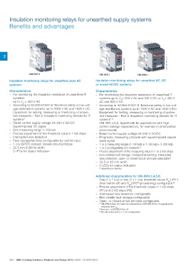
CM-IWS.2 CM-IWS.1 CM-IWN.1
Insulation monitoring relays for unearthed pure AC Insulation monitoring relays for unearthed AC, DC
systems: or mixed AC/DC systems:
Characteristics Characteristics
– For monitoring the insulation resistance of unearthed IT – For monitoring the insulation resistance of unearthed IT
systems: systems up to Un= 250 V AC and 300 V DC or Un= 400 V
up to Un = 400 V AC AC and 600 V DC
– According to IEC/EN 61557-8 "Electrical safety in low volt- – According to IEC/EN 61557-8 "Electrical safety in low volt-
age distribution systems up to 1000 V AC and 1500 V DC: age distribution systems up to 1000 V AC and 1500 V DC:
Equipment for testing, measuring or monitoring of protec- Equipment for testing, measuring or monitoring of protec-
tive measures – Part 8: Insulation monitoring devices for IT tive measures – Part 8: Insulation monitoring devices for IT
systems" systems"1)
– Rated control supply voltage 24–240 V AC/DC – CM-IWN.4,5,6: Specifically for applications with high
– Superimposed DC signal system leakage capacitances, for example in photovoltaic
– One measuring range 1–100 k: environments
– Precise adjustment of the threshold value in 1 k: steps – Rated control supply voltage 24-240 V AC/DC
– Interrupted wire detection – Prognostic measuring principle with superimposed square
– Fault storage/latching configurable by control input wave signal
– 1 c/o (SPDT) contact, closed-circuit principle – 1 or 2 measuring ranges (1-100 k: or 1-100 k: + 2-200 k:)
– 22.5 mm [0.89 in] width – 1 or 2 (configurable) c/o contacts1)
– 3 LEDs for status indication – Precise adjustmemt of the measuring value in 1 or 2 k: steps
– (non-volatile) fault storage, configurable latching, interrupted
wire protection, open- or closed-circuit principle selectable1)
– 22.5 or 45 mm width
– 3 LEDs for status indication
1) depending on devices
Additional characteristics for CM-IWN.1,4,5,6:
– One (1 x 2 c/o) or two (2 x 1 c/o) threshold values Ran1/R11)
(final switch-off) and Ran2/R22) (prewarning) configurable3)
– Precise adjustment of the threshold values in 1 kΩ steps
(R1) and 2 kΩ steps (R2)
– Interrupted wire detection configurable
– Non-volatile fault storage configurable
– Open- or closed-circuit principle configurable
1) CM-IWN.6 does not meet the requirements of IEC/EN 61557-8 regarding the
response time tan.
2) term acc. to IEC/EN 61557-8
3) R2 only active with 2 x 1 c/o configuration
2/61 ABB | Catalog Electronic Products and Relays 2015 | 2CDC 110 004 C0210