
Page 130 - EPR Catalog 2015
P. 130
2CDC 253 021 F0013Insulation monitoring relays for unearthed supply systems
Operating controls
2CDC 253 015 F0013
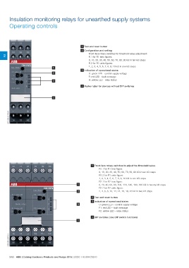
1 Test and reset button
2 Configuration and setting
2 Front-face rotary switches for threshold value adjustment:
R.1 for R1 tens figures:
0, 10, 20, 30, 40, 50, 60, 70, 80, 90 kΩ in ten kΩ steps
R.2 for R1 units figures:
1 1, 2, 3, 4, 5, 6, 7, 8, 9, 10 kΩ in one kΩ steps
3 Indication of operational states
2 U: green LED - control supply voltage
F: red LED - fault message
3 R: yellow LED - relay status
4 Marker label for devices without DIP switches
4
1 Front-face rotary switches to adjust the threshold value:
R1.1 for R1 tens figure:
0, 10, 20, 30, 40, 50, 60, 70, 80, 90 kΩ in ten kΩ steps
R1.2 for R1 units figure:
1, 2, 3, 4, 5, 6, 7, 8, 9, 10 kΩ in one kΩ steps
R2.1 for R2 tens figure:
1 0, 20, 40, 60, 80, 100, 120, 140, 160, 180 kΩ in twenty kΩ steps
R2.2 for R2 units figure:
2 2, 4, 6, 8, 10, 12, 14, 16, 18, 20 kΩ in two kΩ steps
2 Test and reset button
3 Indication of operational states
3 U: green LED – control supply voltage
F1: red LED – fault message
F2: yellow LED – relay status
4 DIP switches (see DIP switch functions)
4
2/63 ABB | Catalog Electronic Products and Relays 2015 | 2CDC 110 004 C0210