
Page 135 - EPR Catalog 2015
P. 135
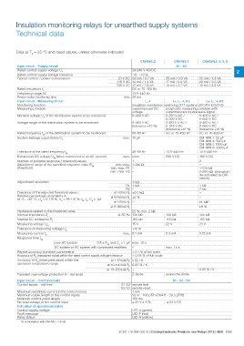
Insulation monitoring relays for unearthed supply systems
Technical data
Data at Ta = 25 °C and rated values, unless otherwise indicated
CM-IWS.2 CM-IWS.1 CM-IWN.1, 4, 5, 6
Input circuit - Supply circuit A1 - A2
Rated control supply voltage Us
Rated control supply voltage tolerance 24-240 V AC/DC 2
Typical current / power consumption
-15...+10 % 35 mA / 0.9 VA 55 mA / 1.3 VA
Rated frequency fs 24 V DC 30 mA / 0.7 VA 17 mA / 2.0 VA 20 mA / 2.3 VA
Frequency range AC 115 V AC 12 mA / 1.4 VA 14 mA / 3.2 VA 15 mA / 3.5 VA
Power failure buffering time 230 V AC 12 mA / 2.8 VA
Input circuit - Measuring circuit
Monitoring function DC or 15-400 Hz
Measuring principle
13.5-440 Hz
Nominal voltage Un of the distribution system to be monitored
min. 20 ms
Voltage range of the distribution system to be monitored
L, w L+, L-, w, KE L+, L-, w, KE
Rated frequency fN of the distribution system to be monitored
System leakage capacitance Ce insulation resistance monitoring of IT systems (IEC/EN 61557-8)
superimposed DC prognostic measuring principle with
voltage superimposed square wave signal
0-400 V AC 0-250 V AC / 0-400 V AC /
0-300 V DC 0-600 V DC
0-460 V AC 0-287.5 V AC / 0-460 V AC /
(tolerance +15 %) 0-345 V DC 0-690 V DC
(tolerance +15 %) (tolerance +15 %)
50-60 Hz DC or 15-400 Hz DC or 15-400 Hz
max. 10 μF CM-IWN.1: 20 μF
CM-IWN.4: 500 μF
CM-IWN.5 1000 μF
CM-IWN.6: 2000 μF
Tolerance of the rated frequency fN 45-65 Hz 13.5-440 Hz 13.5-440 Hz
Extraneous DC voltage Ufg (when connected to an AC system) 290 V DC 460 V DC
Number of possible response / threshold values max. none 2
Adjustment range of the specified response value Ran 100 kȑ –
(threshold) 1 115 kȑ 1-100 kȑ
min.-max. 1-100 ȑ 22 V 2-200 kȑ (activated /
min.-max. R1 – 0.3 mA de-activated by DIP-
min.-max. R2 – max. 15 s switch)
Adjustment resolution 1 kȑ 1 kȑ
2 kȑ
R1 1 kȑ –
–
R2 – ±1 kȑ*
±8 %
Tolerance of the adjusted threshold value / at 1-10 k: RF ±0.5 kȑ
Relative percentage uncertainty A at 10-100 k: RF ±6 % 155 kȑ
at -5...+45 °C, Un = 0-115 %, Us = 85-110 %, fN, fs, Ce = 1μF 185 kȑ
at 1-15 k: RF – 24 V
at 15-200 k: RF – 0.15 mA
Hysteresis related to the threshold value 25 %; min. 2 kȑ
Internal impedance Zi at 50 Hz 135 kȑ
Internal DC resistance Ri 185 kȑ
Measuring voltage Um 15 V
Tolerance of measuring voltage Um +10 %
Measuring current Im max. 0.1 mA
Response time tan
pure AC system 0.5 x Ran and Ce = 1 μF max. 10 s
DC system or AC system with connected rectifiers –
Repeat accuracy (constant parameters) < 0.1 % of full scale
Accuracy of Ra (measured value) within the rated control supply voltage tolerance < 0.05 % of full scale
Accuracy of Ra (measured value) within the at 1-10 kȑ RF 5 : / K –
operation temperature range 0.05 % / K
at 10-100 kȑ RF 0.05 % / K
at 10-200 kȑ RF –
Transient overvoltage protection (w - terminal) Z-diode avalanche diode
Input circuit - Control circuits S1 - S2 - S3
Control inputs - volt free
S1-S3 remote test
Maximum switching current in the control circuit
Maximum cable length to the control inputs S2-S3 remote reset
Minimum control pulse length
No-load voltage at the control input 1 mA
Indication of operational states
Control supply voltage 50 m - 100 pF/m [164 ft - 30.5 pF/ft]
Fault message
Relay status 150 ms
*in combination with CM-IVN ±1.5 kȑ ≤ 24 V ± 5 % ≤ 24 V DC
LED U (green)
LED F (red)
LED R (yellow)
2CDC 110 004 C0210 | Catalog Electronic Products and Relays 2015 | ABB 2/68