
Page 138 - EPR Catalog 2015
P. 138
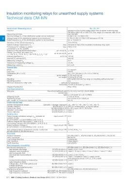
Insulation monitoring relays for unearthed supply systems
Technical data CM-IVN

Input circuit - Measuring circuit                                                                          VL+, VL-, Vw

Function                                                                     expansion of the nominal voltage range of the insulation monitoring relay
Measuring principle                                                          CM-IWN to 690 V AC or 1000 V DC, max. length of connection cable 40 cm
                                                                             see CM-IWN

        Nominal voltage Un of the distribution system to be monitored        0-690 V AC / 0-1000 V DC

2 Voltage range of the distribution system to be monitored                   0-793.5 V AC / 0-1150 V DC (tolerance +15 %)
        Rated frequency fN of the distribution system to be monitored        DC or 15-400 Hz

Tolerance of the rated frequency fN                                             13.5-440 Hz
System leakage capacitance Ce                                          max. identical to that of the insulation monitoring relay used
Extraneous DC voltage Ufg (when                                        max. 793.5 V DC
connected to an AC system)

Tolerance of the adjusted threshold value /                                at 1-15 kΩ RF ±1.5 kΩ
Relative percentage uncertainty A at
-5...+ 45 °C, Un = 0-115 %, Us = 85-110 %, fN, fs, Ce = 1 μF           at 15-200 kΩ RF ±8 %
Internal impedance Zi
Internal DC resistance Ri                                                        at 50 Hz 195 kΩ
Measuring voltage Um                                                                           200 kΩ
Tolerance of measuring voltage Um                                                              24 V
Measuring current Im                                                                           +10 %
                                                                                               0.15 mA

General data

MTBF                                                                         on request

Duty time                                                                    100 %

Dimensions (W x H x D)                                                       45 x 78 x 100 mm (1.78 x 3.07 x 3.94 in)

Weight                                                                 gross weight 0.200 kg (0.441 lb)

Mounting                                                               net weight 0.169 kg (0.373 lb)
Mounting position                                                                      DIN rail (IEC/EN 60715), snap-on mounting without any tool
Minimum distance to other units                                                        any

Degree of protection                                                       vertical not necessary
                                                                       horizontal 10 mm (0.39 in) at Un > 600 V

                                                                                       IP50 / IP20

Electrical connection

Wire size                                                     fine-strand with(out) wire 2 x 0.75-2.5 mm² (2 x 18-14 AWG)
                                                                                 end ferrule
                                                                                          rigid 2 x 0.5-4 mm² (2 x 20-12 AWG)

Stripping length                                                             7 mm (0.28 in)

Tightening torque                                                            0.6-0.8 Nm (5.31-7.08 lb.in)

Max. length of connection cable to CM-IWN                                    40 cm

Environmental data

Ambient temperature ranges                   operation / storage / transport -25...+60 °C / -40...+85 °C / -40...+85 °C
Climatic category                                             IEC/EN 60721-3-3 3K5 (no condensation, no ice formation)
Damp heat, cyclic
Vibration, sinusoidal                                       IEC/EN 60068-2-30 6 x 24 h cycle, 55 °C, 95 % RH
Shock, half-sine                                            IEC/EN 60255-21-1 Class 2
                                                            IEC/EN 60255-21-2 Class 2

Isolation data

Rated impulse withstand voltage Uimp between all              input circuit / PE 8 kV
isolated circuits                                                                      3
(IEC/EN 60947-1, IEC/EN 60664-1,VDE 0110-1)
Pollution degree (IEC/EN 60664-1, VDE 0110-1)

Overvoltage category (IEC/EN 60664-1, VDE 0110-1)                            III

Rated insulation voltage Ui                                   input circuit / PE 1000 V
(IEC/EN 60947-1, IEC/EN 60664-1,VDE 0110-1)

Test voltage between all isolated circuits, routine test      input circuit / PE 3.3 kV, 50 Hz, 1 s
(IEC/EN 60255-5, IEC/EN 61010-1)

Standards

Product standard                                                             IEC/EN 61557-1, IEC/EN 61557-8, IEC/EN 60255-1, EN 50178
Other standards                                                              EN 50178
Low Voltage Directive                                                        2006/95/EC
EMC Directive                                                                2004/108/EC
RoHS Directive                                                               2011/65/EC

Electromagnetic compability

Interference immunity to                                                                IEC/EN 61000-6-1, IEC/EN 61000-6-2, IEC/EN 61326-2-4
    electrostatic discharge                                 IEC/EN 61000-4-2 Level 3, 6 kV / 8 kV
    radiated, radio-frequency,                              IEC/EN 61000-4-3 Level 3, 10 V/m (1 GHz) / 3 V/m (2 GHz) / 1 V/m (2.7 GHz)
    electromagnetic field
    electrical fast transient/burst                         IEC/EN 61000-4-4 Level 3, 2 kV / 5 kHz
    surge                                                   IEC/EN 61000-4-5 Level 3, installation class 3, supply circuit

    conducted disturbances, induced by                                                  and measuring circuit 1 kV L-L, 2 kV L-earth
    radio-frequency fields                                  IEC/EN 61000-4-6 Level 3, 10 V
    voltage dips, short interruptions and
    voltage variations                                     IEC/EN 61000-4-11 Level 3
    harmonics and interharmonics
Interference emission                                      IEC/EN 61000-4-13 Level 3
    high-frequency radiated                                                             IEC/EN 61000-6-3, IEC/EN 61000-6-4
    high-frequency conducted
                                                   IEC/CISPR 22, EN 50022 Class B
                                                   IEC/CISPR 22, EN 50022 Class B

2/71 ABB | Catalog Electronic Products and Relays 2015 | 2CDC 110 004 C0210