Page 134 - EPR Catalog 2015
P. 134

Insulation monitoring relays for unearthed supply systems
Operating state indication, Connection diagrams, DIP switches

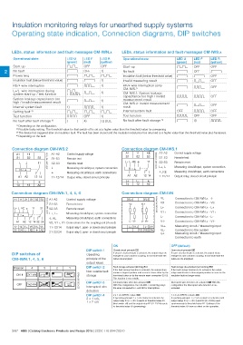
LEDs, status information and fault messages CM-IWN.x                                                             LEDs, status information and fault messages CM-IWS.x

Operational state                                              LED U                        LED F  LED R         Operational state                                              LED U    LED F  LED R
                                                               (green)                      (red)  (yellow)                                                                     (green)  (red)  (yellow)
                                                                                                                 S t a r t- u p                                                 W        OFF    OFF
S t a r t- u p                                                 W OFF                               OFF           No fault                                                                       V
                                                                                                                 Insulation fault (below threshold value)                       V        OFF
2 No fault                                                     V                            OFF    1)            Invalid measuring result                                                V      OFF
        Prewarning                                             V                            W      W                                                                            V        T
                                                                                                                                                                                                OFF
Insulation fault (below threshold value) V V 1)                                                                                                                                 V

KE/w wire interruption                                         VU                                  1)            KE/w wire interruption (only                                   V U OFF
                                                                                                                 CM-IWS.1)
L+/L- wire interruption during                                 W                            T      1)
system start-up / test function                                /X                                                CM-IWS.1: System leakage
                                                                                                   1)            capacitance too high / invalid                                 X X OFF
System leakage capacitance too                                                                     1)            measurement result
high / invalid measurement result                              VT                                  W             CM-IWS.2: Invalid measurement
                                                                                                   1)            result
Internal system fault                                          1)                           X      X                                                                            V        T      OFF
Setting fault 2)                                               W                            W                    Internal system fault
Test function                                                  X                            OFF                                                                                 OFF      X      OFF
No fault after fault storage 3)                                V                            4)                   Test function                                                  X        OFF    OFF
                                                                                                                                                                                V        4)     X
                                                                                                                 No fault after fault storage 3)

1) Depending on the configuration.
2) Possible faulty setting: The threshold value for final switch-off is set at a higher value than the threshold value for prewarning
3) The device has triggered after an insulation fault. The fault has been stored and the insulation resistance has returned to a higher value than the threshold value plus hysteresis.
4) Depending on the fault

Connection diagram CM-IWS.2                                                                                      Connection diagram CM-IWS.1

A1 11                            2CDC 252 102 F0009  A1-A2     Control supply voltage                            A1 11 KE            2CDC 252 103 F0009  A1-A2 Control supply voltage
S1 S2                                                S1-S3     Remote test
                       S3                            S2-S3     Remote reset                                      S1 S2 S3                                S1-S3 Remote test
  Lw                   11
                                                                                                                 L+ L- KE w  11                          S2-S3 Remote reset

 R<w                   12 14                         L         Measuring circuit/input, system connection         R<w        12 14                       L+, L–                 Measuring circuit/input, system connection
                                                     w         Measuring circuit/input, earth connections                                                w, KE                  Measuring circuit/input, earth connections
A1 A2                                                11-12/14  Output relay, closed-circuit principle            A1 A2                                   1-12/14                Output relay, closed-circuit principle

Lw                                                                                                               L+ L-       w

14 12 A2                                                                                                         14 12 A2

Connection diagram CM-IWN.1, 4, 5, 6                                                                             Connection diagram CM-IVN

A1 11 21 S1 S2 S3                2CDC 252 104 F0009  A1-A2     Control supply voltage                            VL+ VL-             2CDC 252 010 F0013  VE Connection to CM-IWN.x - w
                                                                                                                                                         VS Connection to CM-IWN.x - VS
L+ L- KE w 11 21                                     S1-S3     Remote test                                        VL- VL+                                L+ Connection to CM-IWN.x - L+
    R<w
  A1 A2 12 14 22 24                                  S2-S3     Remote reset

12 14 L+ VS V1+ V1-                                  L+, L–    Measuring circuit/input, system connection                                                V1+ Connection to CM-IWN.x - V1+

22 24 L- KE w A2                                     w, KE     Measuring circuit/input, earth connections                                                L- Connection to CM-IWN.x - L-

                                                     VS, V1+, V1 Connections for the coupling unit (if used)     L- V1-      L+ V1+                      V1- Connection to CM-IWN.x - V1-

                                                     11-12/14 Output relay 1, open- or closed-circuit principle  L+ V1+      L- V1-                      VL+                    Measuring circuit / Measuring input

                                                     21-22/24 Output relay 2, open- or closed-circuit principle          VS VE Vw                        VL-                    Connection to the system
                                                                                                                                                         Vw                     Measuring circuit / Measuring input

                                                                                                                                                                                Connection to earth

DIP switches of                                                                             DIP switch 1        ON                                                              OFF (default)
CM-IWN.1, 4, 5, 6                                                                           Operating
                                                                                            principle of the    Closed-circuit principle g                                      Open-circuit principle h
                                                                                            output relays       If closed-circuit principle is selected, the output relays de-  If open-circuit principle is selected, the output relays
                                                                                            DIP switch 2        energize in case a fault is occuring. In non-fault state the    energize in case a fault is occuring. In non-fault state the
                                                                                            Non-volatile fault  relays are energized.                                           relays are de-energized.
                                                                                            storage
Position            4         3                      2         1                                                Fault storage activated (latching) f                            Fault storage de-activated (non latching) e
                                                                                            DIP switch 3        If the fault storage function is activated, the output relays   If the fault storage function is de-activated, the output
ON i u f g                                                              2CDC 252 050 F0b09  Interrupted wire    remain in tripped position until a reset is done either by the  relays switch back to their original position as soon as the
                                                                                            detection           front-face button or by the remote reset connection S2-S3.      insulation fault no longer exists.
OFF j v e h                                                                                 DIP switch 4        This function is non-volatile.
                                                                                            2 x 1 c/o,                                                                          Interrupted wire detection de-activated v With this
                                                                                            1 x 2 c/o           Interrupted wire detection activated u                          configuration the interrupted wire detection is de-
                                                                                                                With this configuration, the CM-IWN.1 monitoring relays         activated.
                                                                                                                the wires connected to w and KE for interruptions.

                                                                                                                2 x 1 c/o (SPDT) contact i                                      1 x 2 c/o (SPDT) contacts j
                                                                                                                If operating principle 2 x 1 c/o contact is selected, the       If operating principle 1 x 2 c/o contacts is selected, both
                                                                                                                output relay R1 (11-12/14) reacts to threshold value R1         output relays R1 (11-12/14) and R2 (21-22/24) react
                                                                                                                (final switch-off) and the output relay R2 (21-22/24) reacts    synchronously to threshold value R1. Settings of the
                                                                                                                to threshold value R2 (prewarning)                              threshold value R2 have no effect on the operation.

2/67 ABB | Catalog Electronic Products and Relays 2015 | 2CDC 110 004 C0210
   129   130   131   132   133   134   135   136   137   138   139