
Page 162 - EPR Catalog 2015
P. 162
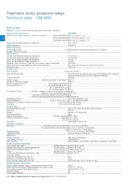
Thermistor motor protection relays
Technical data - CM-MSE

Technical data

Data at Ta = 25 °C and rated values, unless otherwise indicated

Supply circuit - Input circuit                                               CM-MSE

Rated control supply voltage Us power consumption  1SVR550805R9300 24 V AC approx. 1.5 A

2 1SVR550800R9300 110-130 V AC approx. 1.5 A

                                                   1SVR550801R9300 220-240 V AC approx. 1.5 A

Rated control supply voltage Us tolerance                                    -15...+10 %
Rated frequency                                                              50-60 Hz

Measuring circuit                                                     T1-T2 temperature monitoring by means of PTC sensors
                                                                              1
Monitoring function
Number of sensor circuits

Sensor circuit                                                               2.7-3.7 k:
                                                                             1.7-2.3 k:
Temperature threshold (relay de-energizes)                                   <18 :
Temperature hysteresis (relay energizes)                                     >45 :
Short-circuit threshold (relay de-energizes)                                 ͨ1.5 k:
Short-circuit hysteresis (relay energizes)                                   2 x 100 m at 0.75 mm2, 2 x 400 m at 2.5 mm2
Maximum total resistance of sensors connected in series (cold state)
Maximum sensor cable length for short-circuit detection                      <100 ms
Response time

Output circuit                                                        13-14 1 n/o contact
Kind of output

Operational principle                                                        closed-circuit principle (output relay de-energizes if the measured
Contact material                                                             value exceeds/drops below the adjusted threshold)

                                                                             AgCdO

Rated voltage                                     VDE 0110, IEC 664-1, IEC 60947-1 250 V

Maximum switching voltage                                                    250 V

Rated operating current Ie                          AC-12 (resistive) at 230 V 4 A
(IEC/EN 60947-5-1)                                 AC-15 (inductive) at 230 V 3 A

                                                   DC-12 (resistive) at 24 V 4 A

                                                   DC-13 (inductive) at 24 V 2 A

AC Rating (UL 508)              utilization category (Control Circuit Rating Code) B 300

                                                  maximum rated operational voltage 300 V AC

                                maximum continuous thermal current at B 300 5 A

                                maximum making/breaking apparent power at B 300 3600/360 VA

Mechanical lifetime                                                          30 x 106 switching cycles

Electrical lifetime                                at AC12, 230 V AC, 4 A 0.1 x 10⁶ switching cycles

Maximum fuse rating to achieve short-circuit                          n/c contact 10 A fast-acting

protection                                                            n/o contact 10 A fast-acting

General data                                                                               22.5 x 78 x 78.5 mm (0.89 x 3.07 x 3.09 in)
Dimensions (W x H x D)                                                                     100 %
Duty time                                                                                  approx. 0.11 kg (0.24 lb)
Weight                                                                                     any
Mounting position                                              housing / terminals IP50 / IP20
Degree of protection                                                        operation -20...+60 °C
Ambient temperature range                                                      storage -40...+85 °C
                                                                                           DIN rail (IEC/EN 60715)
Mounting

Electrical connection                                 fine strand with wire end ferrule 2 x 1.5 mm2 (2 x 16 AWG)
Wire size                                         fine strand without wire end ferrule 2 x 0.75-1.5 mm2 (2 x 18-16 AWG)

Stripping length                                                                             rigid 2 x 1-1.5 mm2 (2 x 18-16 AWG)
Tightening torque                                                                                   2 x 0.75-1.5 mm2 (2 x 18-16 AWG)
                                                                                                    0.6-0.8 Nm (5.31-7.08 lb.in)

Standards                                                                    IEC 255-6, EN 60255-6
                                                                             2006/95/EC
Product standard                                                             2004/108/EC, 91/263/EEC, 92/31/EEC, 93/68/EEC, 93/67/EEC
Low Voltage Directive
EMC Directive

Electromagnetic compatibility                                  IEC/EN 61000-4-2 Level 3 (6 kV / 8 kV)
                                                               IEC/EN 61000-4-3 Level 3 (10 V/m)
electrostatic discharge                                        IEC/EN 61000-4-4 Level 3 (2 kV / 5 kHz)
radiated, radio-frequency, electromagnetic field               IEC/EN 61000-4-5 Level 3/4 (1/2 kV)
electrical fast transient /burst                               IEC/EN 61000-4-6 Level 3 (10 V)
surge
conducted disturbances, induced by radio-                                                 6g
frequency fields                                                                          10 g
                                                                                          24 h cycle time, 55 °C, 93 % rel., 96 h
Operational reliability (IEC 68-2-6)
Resistance to vibration (IEC 68-2-6)
Environmental testing (IEC 68-2-30)

Electromagnetic compatibility

Rated voltage between supply, measuring and output circuit                   250 V
Rated impulse withstand voltage between all isolated circuits                4 kV / 1.2 - 50 μs
Test voltage between all isolated circuits                                   2.5 kV, 50 Hz, 1 min.
Pollution degree                                                             3
Overvoltage category                                                         III

2/95 ABB | Catalog Electronic Products and Relays 2015 | 2CDC 110 004 C0210