
Page 194 - EPR Catalog 2015
P. 194
General technical data, Accessories, Current transformers
Technical diagrams - CM-range
Load limit curves DC load (resistive)
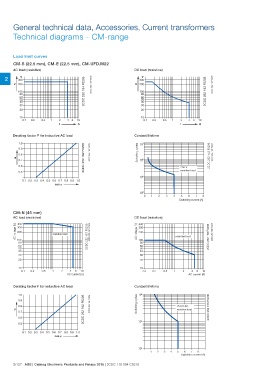
CM-S (22.5 mm), CM-E (22.5 mm), CM-UFD.M22
V
AC load (resistive) 300
V 200
2V 2CDC 252 194 F0205 2CDC 252 193 F0205
300 2CDC 252 194 F0205 2CDC 252 193 F0205
V 200
100 100
80 80
60 60
50 50
40 40
30 30
20 20
10 0.5 1 2 4 6 10 10 0.5 1 2 4 6 10
0.1 0.2 IA 0.1 0.2 IA
Derating factor F for inductive AC load Contact lifetime
1.0 2CDC 252 192 F0205 Switching cycles 2CDC 252 148 F0206
0.9 2CDC 252 192 F0205
0.8 250 V 2CDC 252 148 F0206
F resistive load
0.7
0.6
0.5
0.1 0.2 0.3 0.4 0.5 0.6 0.7 0.8 0.9 1.0
cos ϕ
Switching current [A]
CM-N (45 mm)AC voltage [V] resistive load 2CDC 252 157 F0206 DC load (resistive)AC voltage [V] 2CDC 252 158 F0206
AC load (resistive) 1 2 4 6 10 2CDC 252 157 F0206 400 2CDC 252 158 F0206
AC current [A] 300
400 200
300
200
100 100 resistive load
80 80
60 60 1 2 4 6 10
50 50 AC current [A]
40 40
30 30
20 20
10 0.2 0.5 10 0.2 0.5
0.1 0.1
Derating factor F for inductive AC load Contact lifetime 2CDC 252 156 F0206
106
1.0 2CDC 252 192 F0205 Switching cycles
0.9 2CDC 252 192 F0205 250 V AC
0.8 resistive load
F
0.7 105
0.6
0.5
0.1 0.2 0.3 0.4 0.5 0.6 0.7 0.8 0.9 1.0
cos ϕ
104 12345678
2/127 ABB | Catalog Electronic Products and Relays 2015 | 2CDC 110 004 C0210 Switching current [A]