
Page 190 - EPR Catalog 2015
P. 190
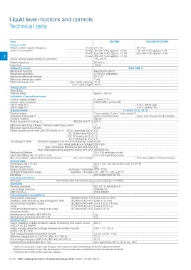
Liquid level monitors and controls
Technical data

Type                                                                                                  CM-ENS                           CM ENS UP/DOWN

         Supply circuit                                        A1-A2 24 V AC                                              24 V AC
        Rated control supply voltage US -                      A1-A2 110-130 V AC approx. 1.5 VA                          110-130 V AC approx. 4 VA
        power consumption                                      A1-A2 220-240 V AC approx. 1.5 VA                          220-240 V AC approx. 4 VA
                                                               A1-A2 380-415 V AC approx. 1.5 VA
2
        Rated control supply voltage US tolerance                        -15...+10 %
        Rated frequency
        Duty time                                                        50-60 Hz
                                                                         100 %

Measuring circuit                                                                                                      MAX-MIN-C

Monitoring function                                                                 liquid level control
Response sensitivity                                                                5-100 k:, adjustable
Maximum electrode voltage                                                           30 V AC
Maximum electrode current                                                           1 mA
Electrode supply line                                 max. cable capacity 10 nF
                                                         max. cable length 100 m

Timing circuit                                                            -
Time delay                                                                approx. 250 ms
Tripping delay

Indication of operational states                                          U: green LED                                    R AL1: yellow LED
                                                                          R MAX/MIN: yellow LED                           R AL2: yellow LED
Control supply voltage                                                    -
Output relay energized                                                    -
Alarm relay AL1
Alarm relay AL2

Output circuits                                                                                                        11-12/14, 21-22, 31-32

Kind of output                                                            1 c/o contact, 1 n/o + 1 n/c contact 2)

Operational principle 1)                                                  open-circuit principle                          open- and closed-circuit principle

Contact material                                                          AgCdo

Rated operational voltage Ue                          (IEC/EN 60947-1) 250 V

Minimum switching voltage / minimum switching current                     -/-

Maximum switching voltage                                                 250 V

Rated operational current Ie (IEC/EN 60947-5-1) AC-12 (resistive) 230 V 4 A
                                                                         AC-15 (inductive) 230 V 3 A

                                                      DC-12 (resistive) 24 V 4 A

                                                      DC-13 (inductive) 24 V 2 A

AC rating (UL 508)        Utilization category (Control Circuit Rating Code) B 300

                                                   max. rated operational voltage 300 V AC

                                   max. continuous thermal current at B 300 5 A

                          max. making/breaking apparent power at B 300 3600/360 VA

Mechanical lifetime                                                       30 x 106 switching cycles

Electrical lifetime (AC-12, 230 V, 4 A)                                   0.3 x 10⁶ switching cycles

Max. fuse rating to achieve short-circuit protection   n/c / n/o contact                                                  10 A fast-acting / 10 A fast-acting

General data                                                                               22.5 x 70 x 100 mm (0.89 x 3.07 x 3.94 in)
Dimensions (W x H x D)                                                                     any
Mounting position                                          enclosure / terminals IP50 / IP20
Degree of protection                                         operation / storage -20...+60 °C / -40...+85 °C
Ambient temperature range                                                                  DIN rail (IEC/EN 60715)
Mounting
                                            fine-strand with wire end ferrule 2 x 2.5 mm2 (2 x 14 AWG)
Electrical connection
Wire size

Standards                                                                 IEC 255-6, EN 60255-6
                                                                          2006/95/EC
Product standard                                                          2004/108/EC
Low Voltage Directive
EMC Directive

Electromagnetic compatibility                                                                                          -

electrostatic discharge                               IEC/EN 61000-4-2 Level 3 (6 kV / 8kV)

radiated, radio-frequency, electromagnetic field      IEC/EN 61000-4-3 Level 3 (10 V/m)

electrical fast transient / burst                     IEC/EN 61000-4-4 Level 3 (2 kV / 5 kHz)

surge                                                 IEC/EN 61000-4-5 Level 4 (2 kV L-L)

conducted disturbances, induced by radio-             IEC/EN 61000-4-6 Level 3 (10 V)
frequency fields

Resistance to vibration (IEC 68-2-6)                                      4g

Mechanical resistance (IEC 68-2-6)                                        6g

Isolation data

Rated insulation voltage between supply, measuring and output circuit 250 V

(VDE 0110, IEC 60947)

Rated impulse withstand voltage between all isolated circuits             4 kV / 1.2 - 50 μs

(VDE0 110, IEC 664)

Test voltage between all isolated circuits                                2,5 kV, 50 Hz, 1 min.

Pollution category (VDE 0110, IEC 664, IEC 255-5)                         3/C

Overvoltage category (VDE 0110, IEC 664, IEC 255-5)                       III / C

Environmental testing (IEC 68-2-30)                                       24 h cycle time, 55 °C, 93 % rel., 96 h

1) Open-circuit principle: Output relay energizes if the measured value exceeds/drops below the adjusted threshold.
Closed-circuit principle: Output relay de-energizes if the measured value exceeds/drops below the adjusted threshold.
2) 1SVR 430 851 R1300 (version with safe isolation)

2/123 ABB | Catalog Electronic Products and Relays 2015 | 2CDC 110 004 C0210