
Page 20 - EPR Catalog 2015
P. 20
CT-D range
Function diagrams
1 Remarks Function of the yellow LED
The yellow LED R glows as soon as the output relay
Legend energizes and turns off when the output relay de-energizes.
G Control supply voltage not applied / Output contact open
B Control supply voltage applied / Output contact closed
A1-Y1/B1 Control input with voltage-related triggering
Terminal designations on the device and in the diagrams
The 1st c/o contact is always designated 15-16/18.
The 2nd c/o contact is designated 25-26/28.
The n/o contacts of the star-delta timers are designated with
17-18 and 17-28.
Control supply voltage is always applied to terminals A1-A2.
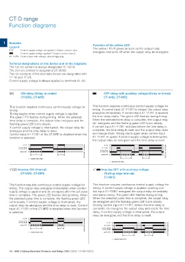
A ON-delay (Delay on make) B OFF-delay with auxiliary voltage (Delay on break)
CT-ERD, CT-MFD CT-AHD, CT-MFD
This function requires continuous control supply voltage for This function requires continuous control supply voltage for
timing. timing. If control input A1-Y1/B1 is closed, the output relay
Timing begins when control supply voltage is applied. energizes immediately. If control input A1-Y1/B1 is opened,
The green LED flashes during timing. When the selected the time delay starts. The green LED flashes during timing.
time delay is complete, the output relay energizes and the When the selected time delay is complete, the output relay
flashing green LED turns steady. de- energizes and the flashing green LED turns steady.
If control supply voltage is interrupted, the output relay de- If control input A1-Y1/B1 recloses before the time delay is
energizes and the time delay is reset. complete, the time delay is reset and the output relay does
Control input A1-Y1/B1 of the CT-MFD is disabled when this not change state. Timing starts again when control input
function is selected. A1-Y1/B1 re-opens.If control supply voltage is interrupted,
the output relay de-energizes and the time delay is reset.
A1-A2 2CDC 252 106 F0206 A1-A2 2CDC 252 107 F0206
15-18, 25-28 A1-Y1/B1
15-16, 25-26 15-18, 25-28
15-16, 25-26
green LED green LED
t <t
t <t
t = adjusted time delay
t = adjusted time delay
CA Impulse-ON (Interval) CB Impulse-OFF with auxiliary voltage
CT-VWD, CT-MFD (Trailing edge interval)
CT-MFD
This function requires continuous control supply voltage for This function requires continuous control supply voltage for
timing. The output relay energizes immediately when control timing. If control supply voltage is applied, opening con-
supply voltage is applied and de-energizes after the set pulse trol input A1-Y1/B1 energizes the output relay immediately
time is complete. The green LED flashes during timing. When and starts timing. The green LED flashes during timing.
the selected pulse time is complete, the flashing green LED When the selected pulse time is complete, the output relay
turns steady. If control supply voltage is interrupted, the de-energizes and the flashing green LED turns steady.
output relay de-energizes and the time delay is reset. Control Closing control input A1-Y1/B1, before the time delay is
input A1-Y1/B1 of the CT-MFD is disabled when this function complete, de-energizes the output relay and resets the time
is selected. delay. If control supply voltage is interrupted, the output
relay de-energizes and the time delay is reset.
A1-A2 2CDC 252 108 F0206 A1-A2 2CDC 252 109 F0206
15-18, 25-28 A1-Y1/B1
15-16, 25-26 15-18, 25-28
15-16, 25-26
green LED green LED
t <t
t = adjusted pulse time
t <t
t = adjusted pulse time
1/9 ABB | Catalog Electronic Products and Relays 2015 | 2CDC 110 004 C0210