Page 22 - EPR Catalog 2015
P. 22

CT-D range
Function diagrams

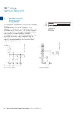
1F     Star-delta change-over
       (Star-delta starting)
       CT-SDD, CT-SAD                                                                       A1-A2                                                             2CDC 252 112 F0206
                                                                                             17-18
This function requires continuous control supply voltage for                                 17-28
timing.
Applying control supply voltage to terminals A1-A2,                                    green LED
energizes the star contactor connected to terminals 17-18
and begins the set starting time t1. The green LED flashes                                              t1                       t2
during timing. When the starting time is complete, the first
output contact de-energizes the star contactor.                                                     t1 = adjusted starting time
Now, the transition time t2 starts. When the transition time                                        t2 = transition time
is complete, the second output contact energizes the                                                CT-SDD: t2 = 50 ms
delta contactor connected to terminals 17-28. The delta                                             CT-SAD: t2 adjustable
contactor remains energized as long as control supply
voltage is applied to the unit.

L1 F3                                              2CDC 252 128 F0b06      L1 L2 L3                                                       2CDC 252 012 F0b07

            95                                                                   135

            96                                                         -F1
            21
                                                                                 246
            22
    F2
        S1

    0

         S2 13                   53                                             135                     135                          135
       I                                                                                            -K3 2 4 6 -K1 2 4 6
                        K2                                             -K2 2 4 6
                    14
                                 54

            K1T         17           17 13 13
                        18
                                           K2 K1                                  154  97 95
                                                                                       98 96
                                     28 14 14                          -F2

                               22           22                                    326

                        K3 21        K1 21

                           A1 A1 A1 A1                                                        -M1   W2
                                                                                                    V2
        K1T K1 K3 K2                                                                   W1           U2

                           A2 A2 A2 A2                                                 V1 M
                                                                                       U1 3 ~
N

                                  Y  ͬ          N
Control circuit diagram
                                                                       Power circuit diagram

1/11 ABB | Catalog Electronic Products and Relays 2015 | 2CDC 110 004 C0210
   17   18   19   20   21   22   23   24   25   26   27