Page 66 - index
P. 66
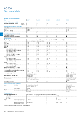
AC500
Technical data
Analog S500 I/O modules
Type AX521 AX522 AI523 AO523 AI531
Number of channels per module
Individual confguration, analog inputs 4 8 16 – 8
outputs 4 8 – 16 –
Signal resolution for channel confguration
-10...+10 V 12 bits + sign 15 bits + sign
0...10 V 12 bits 15 bits
0...20 mA, 4...20 mA 12 bits 15 bits
Temperature: 0.1 °C ? ? ? ? ?
4 Monitoring confguration per channel
Plausibility monitoring ? ? ? ? ?
Wire break & short-circuit monitoring ? ? ? ? ?
Analog Inputs AI
Signal confguration per AI max. number per module and with regard to the configuration: AIs / Measuring points (depending on the use of
2/3-wire connection or differential input)
0...10 V 4 / 4 8 / 8 16 / 16 – 8 / 8
-10...+10 V 4 / 4 8 / 8 16 / 16 – 8 / 8
0...20 mA 4 / 4 8 / 8 16 / 16 – 8 / 8
4...20 mA 4 / 4 8 / 8 16 / 16 – 8 / 8
Pt100
-50...+400 °C (2-wire) 4 / 4 8 / 8 16 / 16 – 8 / 8
-50...+400 °C (3-wire), 2 channels 4 / 2 8 / 4 16 / 8 – 8 / 8
-50...+400 °C (4-wire) – – – – 8 / 8
-50...+70 °C (2-wire) 4 / 4 8 / 8 16 / 16 – 8 / 8
-50...+70 °C (3-wire), 2 channels 4 / 2 8 / 4 16 / 8 – 8 / 8
-50...+70 °C (4-wire) – – – – 8 / 8
Pt1000
-50...+400 °C (2-wire) 4 / 4 8 / 8 16 / 16 – 8 / 8
-50...+400 °C (3-wire), 2 channels 4 / 2 8 / 4 16 / 8 – 8 / 8
-50...+400 °C (4-wire) – – – – 8 / 8
Ni1000
-50...+150 °C (2-wire) 4 / 4 8 / 8 16 / 16 – 8 / 8
-50...+150 °C (3-wire), 2 channels 4 / 2 8 / 4 16 / 8 – 8 / 8
-50...+150 °C (4-wire) – – – – 8 / 8
Thermocouples of types J, K, T, N, S – – – – ?
0...10 V using differential inputs, 2 channels 4 / 2 8 / 4 16 / 8 – 8 / 8
-10...+10 V using differential inputs, 2 channels 4 / 2 8 / 4 16 / 8 – 8 / 8
Digital signals (digital input) 4 / 4 8 / 8 16 / 16 – 8 / 8
Input resistance per channel voltage: > 100 kO – voltage: > 100 kO
current: approx. 330 O current: approx. 330 O
Time constant of the input flter voltage: 100 µs – voltage: 100 µs
current: 100 µs current: 100 µs
Conversion cycle 2 ms (for 8 AI + 8 AO), – 1 ms (for 8 AI + 8 AO),
1 s for Pt100/1000, Ni1000 1 s for Pt100/1000,
Ni1000
Overvoltage protection ? ? ? – ?
Data when using the AI as digital input
Input time delay 8 ms typically, configurable – 8 ms typically,
from 0.1 up to 32 ms configurable from 0.1
up to 32 ms
signal voltage 24 V DC – 24 V DC
Signal 0 -30...+5 V – -30...+5 V
1 13...30 V – 13...30 V
Analog outputs AO
Possible confguration per AO Max. number of AOs per module and with regard to the configuration:
-10...+10 V 4 8 (1) – 16 (1) –
0...20 mA 4 – 8 –
4...20 mA 4 – 8 –
Output resistance (burden) when 0...500 O – 0...500 O –
used as current output
loading capability when Max. ±10 mA – Max. ±10 mA –
used as voltage output
(1) Half can be used on current (the other half remains available).
4/64 | ABB Industrial Automation & Motion