Page 68 - index
P. 68
AC500
Technical data
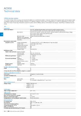
CD522 encoder module
The CD522 module offers accuracy and dynamic fexibility for a customized solution. It has two independent encoder inputs onboard and is easily
confgured using the Automation Builder software for 10 different operation modes and for frequencies up to 300 kHz (depending on CPU cycle
time). The CD522 module also integrates outputs for pulses and for PWM as well as normal inputs and outputs, depending on selected encoder
mode.
Type CD522
Functionality
Digital inputs/outputs 24 V DC, dedicated inputs/outputs can be used for specific counting functions.
All unused inputs/outputs can be used as input/output with standard specification.
Input options Catch/Touch operation, counter value stored in separate variable on external event (rising or falling)
4 Set to preset counter register with predefined value
Set to reset counter register
End value output Output set when predefined value is reached
Reference point initialization ?
(RPI) input for relative encoder
initialization
High-speed counter/encoder
Integrated counters Counter characteristics 2 counters (24 V DC, 5 V DC, differential and 1 Vpp sinus input)
Counter mode one 32 bits or two 16 bits
Relative position encoder X1, X2, X3
Absolute SSI encoder ?
Time frequency meter ?
Frequency input up to 300 kHz
PWM/pulse outputs
Output mode specifcation Number of outputs 2
Push pull output 24 V DC, 100 mA max
Current limitation Thermal and overcurrent
PWM mode specifcation Frequency 1…100 kHz
Value 0...100 %
Pulse mode specifcation Frequency 1…15 kHz
Pulse emission 1…65535 pulses
Number of pulses emitted 0...100 %
indicator
Frequency mode Frequency output 100 kHz
specifcation Duty Cycle Set to 50 %
Number of channels per module
Digital input 2
output 2
Confgurable channels DC (confgurable as inputs or outputs) 8
Additional confguration of channels as
Fast counter Integrated 2 counter encoders
Connection via terminal unit ?
Digital Inputs
Input signal voltage 24 V DC
time delay 8 ms typically configurable from 0.1 up to 32 ms
Input current per channel
At input voltage 24 V DC Typically 5 mA
5 V DC > 1 mA
15 V DC > 5 mA
30 V DC < 8 mA
Digital outputs
Output voltage at signal state 1 UP – 0.8 V
Output current
Nominal current per channel 0.5 A at UP = 24 V
Maximum (total current of all channels) 8 A
Residual current at signal state 0 < 0.5 mA
Demagnetization when switching off inductive loads By internal varistors
Switching frequency
For inductive load Max. 0.5 Hz
For lamp load Max. 11 Hz with max. 5 W
Short-circuit / Overload proofness ?
Overload indication (I > 0.7 A) After approx. 100 ms
Output current limiting ?
Proofness against reverse feeding of 24 V signals ?
4/66 | ABB Industrial Automation & Motion