Page 73 - index
P. 73
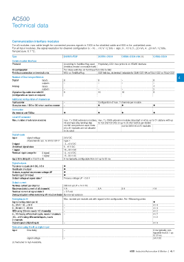
AC500
Technical data
Communication interface modules
For all modules: max cable length for connected process signals is 1000 m for shielded cable and 600 m for unshielded ones.
For all Input modules, the signal resolution for channel confguration is: -10…+10 V: 12 bits + sign; 0…10 V, 0…20 mA, 4…20 mA: 12 bits.
Temperature: 0.1 °C.
Type DC505-FBP DC551-CS31 CI590-CS31-HA (1) CI592-CS31
Communication Interface
Protocol According to FieldBusPlug used Proprietary CS31 bus protocol on RS485 interface
(Fieldbus neutral on module itself)
ID confguration Per rotary switches on front face from 00d to 99d
Field bus connection on terminal units M12 on FieldBusPlug CS31 field bus, via terminal / redundant for CI590-CS31-HA on TU551-CS31 or TU552-CS31
Number of Channels per Module 4
Digital inputs 8 8 – 8
outputs – – – –
Analog inputs – – – 4
outputs – – – 2
Digital confgurable channels DC 8 16 16 8
(confgurable as inputs or outputs)
Additional confguration of channels as
Fast counter – Configuration of max. 2 channels per module
Occupies max. 1 DO or DC when used as counter – ? ? ?
Connection
Via terminal unit TU5xx ? ? ? ?
Local I/O extension
Max. number of extension modules max. 7 x S500 extension modules, max. 7 x S500 extension modules (standard or eCo), up to 31 stations with up
nb and type (dig./analog) dep. to 120 DIs/120 DOs or up to 32 AIs/ 32AOs per station
on FBP and protocol used. Note: not for S500-eCo I/O modules
eCo I/O modules are not allowed
to be used
Digital inputs
Input signal voltage 24 V DC
characteristic acc. to EN 61132-2 Type 1
0 signal -3...+5 V DC
Undefned signal state 5...15 V DC
1 signal 15...30 V DC
Residual ripple, range for 0 signal -3...+5 V DC
1 signal 15...30 V DC
Input time delay (0 -> 1 or 1 -> 0) 8 ms typically, configurable from 0.1 up to 32 ms
Digital outputs
Transistor outputs 24 V DC, 0.5 A ?
Readback of output ?
Outputs, supplied via process voltage UP ?
Switching of 24 V load ?
Output voltage at signal state 1 Process voltage UP - 0.8 V
Output current
Nominal current per channel 500 mA at UP = 24 V DC
Maximum (total current of all channels) 4 A 8 A 8 A 4 A
Residual current at signal state 0 < 0.5 mA
Demagnetization when switching off inductive loads By internal varistors
Analog inputs AI Max. number per module and with regard to the configuration: AIs / Measuring points
Signal confguration per AI – ?
0…10 V / -10…+10 V – 4 / 4
0…20 mA / 4…20 mA – 4 / 4
RTD using 2/3 wire needs 1/2 channel(s) – 4 / 2
0…10 V using differential inputs, needs 2 channels – 4 / 2
-10…+10 V using differential inputs, needs – 4 / 2
2 channels
Digital signals (digital input) – 4 / 4
Data when using the AI as digital input
Input time delay – 8 ms typically, con-
figurable from 0.1 up
to 32 ms
signal voltage – 24 V DC
(1) Dedicated to High Availability.
ABB Industrial Automation & Motion | 4/71