
Page 132 - PLC Automation
P. 132
130 MAIN CATALOG PLC AUTOMATION
—
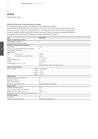
AC500
Technical data
DC541-CM interrupt I/O and fast counter module
In the operating mode counter, the channels can be configured as follows:
Input, Output, 32-bit up/down counter (uses C0...C3) as a 32-bit counter without limit, 32-bit periodic
counter as a 32-bit counter with a limit, limiter for a 32-bit counter (limit channel 0), 32-bit up counter
(forward counter) with the frequencies 50 kHz, 5 kHz and 2.5 kHz, pulse-width modulation (PWM) with
a resolution of 10 kHz, time and frequency measurement, frequency output.
Type DC541-CM
Number of channels per module
Configurable channels DC 8
(configurable as inputs or outputs)
Additional configuration of channels as
Fast counter Yes
Connection via CPU terminal base. Occupies one
communication module slot
04
Digital inputs
Input signal voltage 24 V DC
characteristic acc. to EN 61132-2 Type 1
0 signal -3...+5 V DC
Undefined signal state 5...15 V DC
1 signal 5...30 V DC
Input time delay (0 -> 1 or 1 -> 0) 20 µs
Clamp to clamp - 300 µs with interrupt task
Input current per channel
At input voltage 24 V DC 5 mA typically
5 V DC > 1 mA
15 V DC > 5 mA
30 V DC < 8 mA
Digital outputs
Transistor outputs 24 V DC, 0.5 A
Readback of output
Switching of 24 V load
Output voltage at signal state 1 Process voltage UP minus 0.8 V
Output current
Nominal current per channel 0.5 A
Maximum (total current of all channels) 4 A
Residual current at signal state 0 < 0.5 mA
Demagnetization when switching off inductive loads yes
Potential isolation
Per module
Voltage supply for the module Internally via backplane bus