
Page 149 - PLC Automation
P. 149
AC500 – HIGH PERFORMANCE MODUL AR PLC 147
—
AC500
Technical data
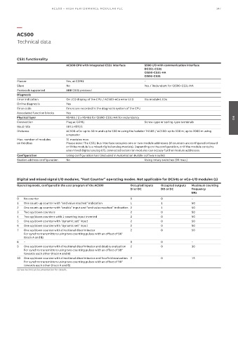
CS31 functionality
AC500 CPU with integrated CS31 interface S500 I/O with communication interface
DC551-CS31
CI590-CS31-HA
CI592-CS31
Master Yes, at COM1 –
Slave No Yes / Redundant for CI590-CS31-HA
Protocols supported ABB CS31 protocol
Diagnosis
Error indication On LCD display of the CPU / AC500-eCo error LED Via module LEDs
Online diagnosis Yes
Error code Errors are recorded in the diagnosis system of the CPU
Associated function blocks Yes
Physical layer RS485 / 2 x RS485 for CI590-CS31-HA for redundancy 04
Connection Plug at COM1 Screw-type or spring-type terminals
Baud rate 187.5 kbit/s
Distance AC500-eCo: up to 50 m and up to 500 m using the isolator TK506 / AC500: up to 500 m; up to 2000 m using
a repeater
Max. number of modules 31 modules max.
on fieldbus Please note: The CS31 bus interface occupies one or two module addresses (if counters are configured onboard
or if the module is a mixed digital analog module). Depending on the configuration, or if the module contains
also mixed digital analog I/O, connected extension modules can occupy further module addresses.
Configuration Using configuration tool (included in Automation Builder software suite)
Station address configuration No Using rotary switches (99 max.)
Digital and mixed signal I/O modules, “Fast Counter” operating modes. Not applicable for DC541 or eCo-I/O modules (1)
Operating mode, configured in the user program of the AC500 Occupied inputs Occupied outputs Maximum counting
DI or DC DO or DC frequency
kHz
0 No counter 0 0 –
1 One count-up counter with “end value reached” indication 1 1 50
2 One count-up counter with “enable” input and “end value reached” indication 2 1 50
3 Two up/down counters 2 0 50
4 Two up/down counters with 1 counting input inverted 2 0 50
5 One up/down counter with “dynamic set” input 2 0 50
6 One up/down counter with “dynamic set” input 2 0 50
7 One up/down counter with directional discriminator 2 0 50
For synchro transmitters using two counting pulses with an offset of 90°
(track A and B)
8 – 0 0 –
9 One up/down counter with directional discriminator and double evaluation 2 0 30
For synchro transmitters using two counting pulses with an offset of 90°
towards each other (track A and B)
10 One up/down counter with directional discriminator and fourfold evaluation 2 0 15
For synchro transmitters using two counting pulses with an offset of 90°
towards each other (track A and B)
(1) See technical documentation for details.