
Page 150 - PLC Automation
P. 150
148 MAIN CATALOG PLC AUTOMATION
—
AC500
System data
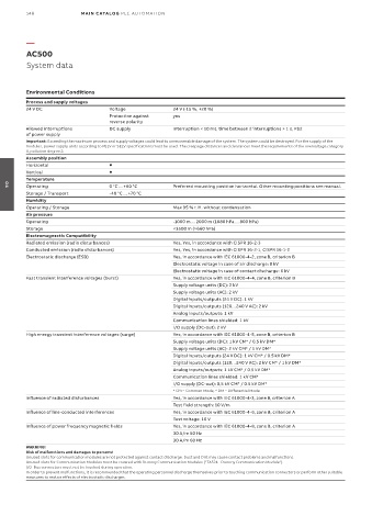
Environmental Conditions
Process and supply voltages
24 V DC Voltage 24 V (-15 %, +20 %)
Protection against yes
reverse polarity
Allowed interruptions DC supply Interruption < 10 ms, time between 2 interruptions > 1 s, PS2
of power supply
Important: Exceeding the maximum process and supply voltages could lead to unrecoverable damage of the system. The system could be destroyed. For the supply of the
modules, power supply units according to PELV or SELV specifications must be used. The creepage distances and clearances meet the requirements of the overvoltage category
II, pollution degree 2.
Assembly position
Horizontal
Vertical
Temperature
Operating 0 °C ... +60 °C Preferred mounting position horizontal. Other mounting positions see manual.
04
Storage / Transport -40 °C ... +70 °C
Humidity
Operating / Storage Max 95 % r. H. without condensation
Air pressure
Operating -1000 m ... 2000 m (1080 hPa ... 800 hPa)
Storage <3500 m (>660 hPa)
Electromagnectic Compatibility
Radiated emission (radio disturbances) Yes, Yes, in accordance with CISPR 16-2-3
Conducted emission (radio disturbances) Yes, Yes, in accordance with CISPR 16-2-1, CISPR 16-1-2
Electrostatic discharge (ESD) Yes, in accordance with IEC 61000-4-2, zone B, criterion B
Electrostatic voltage in case of air discharge: 8 kV
Electrostatic voltage in case of contact discharge: 6 kV
Fast transient interference voltages (burst) Yes, in accordance with IEC 61000-4-4, zone B, criterion B
Supply voltage units (DC): 2 kV
Supply voltage units (AC): 2 kV
Digital inputs/outputs (24 V DC): 1 kV
Digital inputs/outputs (120…240 V AC): 2 kV
Analog inputs/outputs: 1 kV
Communication lines shielded: 1 kV
I/O supply (DC-out): 2 kV
High energy transient interference voltages (surge) Yes, in accordance with IEC 61000-4-5, zone B, criterion B
Supply voltage units (DC): 1 kV CM* / 0.5 kV DM*
Supply voltage units (AC): 2 kV CM* / 1 kV DM*
Digital inputs/outputs (24 V DC): 1 kV CM* / 0.5 kV DM*
Digital inputs/outputs (120…240 V AC): 2 kV CM* / 1 kV DM*
Analog inputs/outputs: 1 kV CM* / 0.5 kV DM*
Communication lines shielded: 1 kV CM*
I/O supply (DC-out): 0,5 kV CM* / 0.5 kV DM*
* CM = Common Mode, * DM = Differential Mode
Influence of radiated disturbances Yes, in accordance with IEC 61000-4-3, zone B, criterion A
Test field strength: 10 V/m
Influence of line-conducted interferences Yes, in accordance with IEC 61000-4-6, zone B, criterion A
Test voltage: 10 V
Influence of power frequency magnetic fields Yes, in accordance with IEC 61000-4-8, zone B, criterion A
30 A/m 50 Hz
30 A/m 60 Hz
WARNING!
Risk of malfunctions and damages to persons!
Unused slots for communication modules are not protected against contact discharge. Dust and Dirt may cause contact problems and malfunctions.
Unused slots for Communication Modules must be covered with Dummy Communication Modules ("TA524 - Dummy Communication Module”).
I/O-Bus connectors must not be touched during operation.
In order to prevent malfunctions, it is recommended that the operating personnel discharge themselves prior to touching communication connectors or perform other suitable
measures to reduce effects of electrostatic discharges.