
Page 145 - PLC Automation
P. 145
AC500 – HIGH PERFORMANCE MODUL AR PLC 143
—
AC500
Technical data
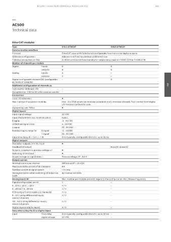
EtherCAT modules
Type CI511-ETHCAT CI512-ETHCAT
Communication interface
Protocol EtherCAT slave with CAM-Switch configurable function on the digital outputs
ID Device configuration Address is defined by position on Ethernet bus
Field bus connection on TUs 2 x RJ45 with switch functionality for simple daisy chain on TU507-ETH or TU508-ETH
Number of channels per module
Digital inputs 8 8
outputs 8 8
Analog inputs 4 –
outputs 2 –
Digital configurable channels DC (configurable – 8
as inputs or outputs)
Additional configuration of channels as 04
Fast counter (onboard I/O) –
Occupies max. 1 DO or DC when used as counter –
Connection
Local I/O extension
Max. number of extension modules max. 10 x S500 extension modules (standard or eCo modules allowed). Fast counter from digital
I/O modules can be also used.
Via terminal unit TU5xx
Digital inputs
Input signal voltage 24 V DC
Input characteristic acc. to EN 61 132-2 Type 1
0 signal -3...+5 V DC
Undefined signal state 5...15 V DC
1 signal 15...30 V DC
Residual ripple, range for 0 signal -3...+5 V DC
1 signal 15...30 V DC
Input time delay (0 -> 1 or 1 -> 0) 8 ms typically, configurable from 0.1 up to 32 ms
Digital outputs
Transistor outputs 24 V DC, 0.5 A
Readback of output – (on DC outputs)
Outputs, supplied via process voltage UP
Switching of 24 V load
Output voltage at signal state 1 Process voltage UP - 0.8 V
Output current
Nominal current per channel 500 mA at UP = 24 V DC
Maximum (total current of all channels) 8 A
Residual current at signal state 0 < 0.5 mA
Demagnetization when switching off inductive By internal varistors
loads
Analog inputs AI Max. number per module and with regard to the configuration: AIs / Measuring points
Signal configuration per AI 4 –
0…10 V / -10 V… +10 V 4 / 4 –
0…20 mA / 4…20 mA 4 / 4 –
RTD using 2/3 wire needs 1/2 channel(s) 4 / 2 –
0…10 V using differential inputs, 4 / 2 –
needs 2 channels
-10…+10 V using differential inputs, 4 / 2 –
needs 2 channels
Digital signals (digital input) 4 / 4 –
Data when using the AI as digital input
Input time delay 8 ms typically, configurable from 0.1 up to 32 ms –
signal voltage 24 V DC –