
Page 141 - PLC Automation
P. 141
AC500 – HIGH PERFORMANCE MODUL AR PLC 139
—
AC500
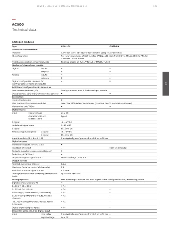
Technical data
CANopen modules
Type CI581-CN CI582-CN
Communication interface
Protocol CANopen slave, DS401 profile selectable using rotary switches
ID configuration Per rotary switches on front face for CANopen ID node from 00h to 7Fh and 80h to FFh for
CANopen DS401 profile
Field bus connection on terminal units Terminal blocks on TU517/TU518 or TU509/TU510
Number of channels per module
Digital inputs 8 8
outputs 8 8
Analog inputs 4 –
outputs 2 –
Digital configurable channels DC – 8
(configurable as inputs or outputs) 04
Additional configuration of channels as
Fast counter (onboard I/O) Configuration of max. 2 DI channels per module
Occupies max. 1 DO or DC when used as counter
Connection
Local I/O extension
Max. number of extension modules max. 10 x S500 extension modules (standard or eCo modules are allowed)
Via terminal unit TU5xx
Digital inputs
Input signal voltage 24 V DC
characteristic acc. Type 1
to EN 61132-2
0 signal -3...+5 V DC
Undefined signal state 5...15 V DC
1 signal 15...30 V DC
Residual ripple, range for 0 signal -3...+5 V DC
1 signal 15...30 V DC
Input time delay (0 -> 1 or 1 -> 0) 8 ms typically, configurable from 0.1 up to 32 ms
Digital outputs
Transistor outputs 24 V DC, 0.5 A
Readback of output – (on DC outputs)
Outputs, supplied via process voltage UP
Switching of 24 V load
Output voltage at signal state 1 Process voltage UP - 0.8 V
Output current
Nominal current per channel 0.5 A
Maximum (total current of all channels) 8 A
Residual current at signal state 0 < 0.5 mA
Demagnetization when switching off inductive By internal varistors
loads
Analog Inputs AI Max. number per module and with regard to the configuration: AIs / Measuring points
Signal configuration per AI 4 –
0…10 V / -10…+10 V 4 / 4 –
0…20 mA / 4…20 mA 4 / 4 –
RTD using 2/3 wire needs 1/2 channel(s) 4 / 2 –
0…10 V using differential inputs, needs 2 4 / 2 –
channels
-10…+10 V using differential inputs, needs 4 / 2 –
2 channels
Digital signals (digital input) 4 / 4 –
Data when using the AI as digital input
Input time delay 8 ms typically, configurable from 0.1 up to 32 ms –
signal voltage 24 V DC –