
Page 489 - Entrelec Terminal Blocks Master Catalog
P. 489
MTC6 thermocouple terminal blocks
Screw clamp - 6 mm 0.236 in spacing
Description
– Universal terminal block adapted to all type of thermocouples,
– Allow thermocouple wire extention with no loss of signal integrity,
– Compatible with solid type thermocouple wires,
– Reduced inventory: only one part number needed for all configurations.
Ordering details
Description Color Type Part Number Pkg Weight
1SNC161032F0014 Feed-through Grey MTC6 1SNA115206R2200 50 20
(1 pce) g
pce
MTC6.Ex
1SNA146227R2500
50
20
Main technical data Mounting instructions
NFC DIN Rail G32, TH 35-7.5,
TH 35-15
Wire size 2 rigid thermocouple conductors Wire stripping 31 mm
MTC6 0.9 to 1.5 length 1.22 in
Rated voltage 500 V
Rated voltage Ex e (MTC6.Ex) 550 V IEC/EN 60079-7 - IM2/M1 II 2 GD/1 GD Ex e I/II Torque 0.4 - 0.6 N.m
3.5 - 5.3 lb.in
44.5 1.75"
The connecting capacity data for one Rigid: Solid/Stranded, or one Flexible conductor (when applicable) is a mandatory information required by IEC, UL and CSA standards (Copper conductors).
All other data are provided as supplementary information only. For more details, please consult our CB, UL or CSA certificates and technical datasheet available on http://www.TE.com
55.5 2.18" RoHS Gost R
53 2.08" Notes
48 1.88"
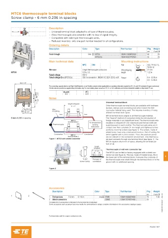
Universal terminal block
length stripped
31 1.22" Other thermocouple terminal blocks are available with hardware
(screws, clamps and connecting bar) which match the ther-
18 0.71" Wire mocouple material being used. This requires inventory of many
23 0.91" insulating
different terminal block types.
Iron Iron
MTC6 terminal block adapts to all thermocouple material.
6 mm 0.236 in spacing This "neutral" method of connection limits the introduction of
MTC 6 foreign materials to an insignificant level. The thermocouple wire
Terminal block 1
To temperature insulation is stripped (31 mm maximum) and the bar wires are
Thermocouple sensing superimposed on each another. The thermocouple wires are in
instrument
contact over their complete 31 mm length and tightened at two
points by round tip screws (see figure 1). The screws, made of
plated brass, have only a mechanical function, that of holding the
Constantan Constantan wires together with a point contact. Thus, the pressure points
MTC 6
Terminal block 2 are not relevant in the connection environment. One thermocou-
Figure 1: MTC6 with shield connector ple lead connects through one terminal block (see figure 1). The
MTC6 requires only 6 mm of space, allowing 50 terminals per
foot of rail.
1.6 0.06" length
stripped
Thermocouple shield wire connector bar
31 1.22"
3.3 0.13" The MTC6 can be field or factory equipped with a shield con-
nector bar (see figure 2). This bar, made of treated brass, fits in
the lower part of the terminal block. It ensures the continuity of 9
90° Principle of the thermocouple wire shield through the terminal block or to the
Screw clamp connection ground with no additional spacing.
Figure 2
Accessories
Description Color Type Part Number Pkg Weight
1SNC161121S0201 - Rev. B
pce (1 pce) g
1 2
1 End sections 2.8 mm 0.110 in Grey FEM6 1SNA118368R1600 20 2.40
2 Shield connectors CBM5 1SNA178745R1400 50
Complete list of accessories is indicated in the terminal block datasheet.
Some accessories such as jumper bars may modify the terminal block’s ratings: complete information in the accessories catalogue pages.
Technical data valid for copper conductors only.
PAGE 197