
Page 109 - Motor_protection_and_control_Manual_motor_starters_ contactors
P. 109
B6, B7, BC6, BC7, TBC7 3- and 4-pole mini contactors
VB6, VB7, VBC6, VBC7 3- and 4-pole mini reversing contactors
Technical data
Magnet system characteristics for B6, B7 contactors
Contactor types AC operated B6, VB6 B7, VB7
Coil operating limits acc. to IEC 60947-4-1 AC supply 0.85 ... 1.1 x U c
AC control voltage
Rated control circuit voltage U C See ordering tables
Coil consumption Average pull-in value 3.5 VA / 3.5 W
Average holding value 3.5 VA / 3.5 W
Drop-out voltage 0.20 ... 0.75 % of U
3
c
Magnet system characteristics for BC6, BC7 contactors
Contactor types DC operated BC6, VBC6 BC7, VBC7
Coil operating limits acc. to IEC 60947-4-1 DC supply 0.85 ... 1.1 x U
c
AC control voltage
Rated control circuit voltage U C See ordering tables
Coil consumption 1) Average pull-in value 3.5 VA / 3.5 W
Average holding value 3.5 VA / 3.5 W
Drop-out voltage in % of U C min 0.10 ... 0.75 x U C
1) Interface mini-contactors: see coil consumption on ordering details pages
Magnet system characteristics for TBC7 contactors
Contactor types DC operated TBC7
Coil operating limits acc. to IEC 60947-4-1 DC supply Wide range voltage supply see ordering tables, U Cmin ... U Cmax
AC control voltage
Rated control circuit voltage U C See ordering tables
Coil consumption Average pull-in value 5 VA / 5 W
Average holding value 5 VA / 5 W
Drop-out voltage in % of U ≤ 0.20 % of U
C min Cmin
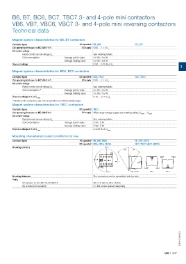
Mounting characteristics and conditions for use
Contactor types AC operated B6, VB6, VB6A B7, VB7, VB7A
DC operated BC6, VBC6, VBC6A BC7, TBC7, VBC7, VBC7A
Mounting positions Pos. 2
+ 30° - 30°
Pos. 4
Pos. 3
Pos. 1 Pos. 1 ± 30° Pos. 5 Pos. 6
Mounting distances The contactors can be assembled side by side
Fixing
On rail acc. to IEC 60715, EN 60715 35 x 7.5 mm or 35 x 15 mm
By screws (not supplied) 2 x M4 screws placed diagonally
2CDC102043C0201
ABB | 3/47