
Page 246 - Motor_protection_and_control_Manual_motor_starters_ contactors
P. 246
DOL and reversing starters protected by overload relays
With AF contactors - Open type version in kit form
Switching frequency diagrams
General
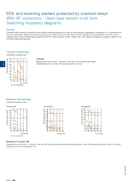
Overload relays cannot be operated at any arbitrary switching frequency in order to avoid tripping. Applications involving up to 15 operations per
hour are acceptable. Higher switching frequencies are permitted if the duty ratio and the motor starting time are allowed for and if the motor's
making current does not appreciably exceed 6 times the rated operating current. Please refer to the adjacent diagram for guideline values for the
permitted switching frequency.
Thermal overload relay
Intermittent periodic duty Example:
140
Switching frequency (ops/h) 80 t = 0.5 s
5 120 Starting time of the motor: 1 second - Duty ratio: 40 % means a permitted
switching frequency of max. 60 operating cycles per hour.
100
a
60
a
a
40 t = 3 s t = 1 s
t = 1.5 s
a
20 t = 5 s
a
0
0 20 40 60 80 100
Duty ratio (%)
ta: motor starting time
Electronic overload relay
Intermittent periodic duty
Trip class 10E Trip class 20E Trip class 30E
50 t = 5 s
a
45
a
Switching frequency (ops/h) 140 t = 1 s Switching frequency (ops/h) 70 Switching frequency (ops/h) 35 t = 10 s
160
80
t = 0.5 s
a
40
t = 2 s
120
60
30
100
50
25
a
80
40
a
20
a
60
a
a
a
t = 6 s
20
40 t = 1.5 s 30 t = 4 s 15 t = 15 s
10
a
a
a
t = 3 s a t = 8 s t = 20 s
20 10 t = 10 s 5
a
a
t = 5 s t = 25 s
a
t = 12 s
0 0 0
0 20 40 60 80 100 0 20 40 60 80 100 0 20 40 60 80 100
Duty ratio (%) Duty ratio (%) Duty ratio (%)
ta: motor starting time
Exemple for trip class 10E:
Starting time of the motor: 1 second. Duty ratio: 60 % means a permitted switching frequency of max. 60 operating cycles per hour, for a motor
breaking current not exceeding 6 x In.
1SBC101954S0201
5/46 | ABB