
Page 424 - Motor_protection_and_control_Manual_motor_starters_ contactors
P. 424
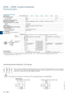
AF09 ... AF80  4-pole contactors

       Technical data


       General technical data
       Contactor types             AC / DC operated AF09  AF16  AF26    AF38     AF40    AF52     AF80
       Rated insulation voltage Ui
         acc. to IEC 60947-4-1                 690 V                                              1000 V
         acc. to UL / CSA                      600 V
       Rated impulse withstand voltage Uimp.   6 kV                                               8 kV
       Electromagnetic compatibility           Devices complying with IEC 60947-1 / EN 60947-1 - Environment A and B (1)
       Ambient air temperature close to contactor
         Operation                             -40...+70 °C
         Storage                               -60...+80 °C
       Climatic withstand                      Category B according to IEC 60947-1 Annex Q
       Maximum operating altitude (without derating)  3000 m
       Mechanical durability
         Number of operating cycles            10 millions operating cycles
         Max. switching frequency              3600 cycles/h
       Shock withstand
    5  acc. to IEC 60068-2-27 and EN 60068-2-27
       Mounting position 1
                                    Shock direction  1/2 sinusoidal shock for 11 ms: no change in contact position, closed or open position
                           4 N.O.           A 30 g                               20 g
                           Main poles       B1 25 g Closed position / 5 g Open position  20 g Closed position / 5 g Open position
                                            B2 15 g                              10 g
                                            C1 25 g                              20 g
                      C1                    C2 25 g                              20 g
                           2 N.O. + 2 N.C.  A 30 g              30 g Closed position /    20 g
                           Main poles                           25 g Open position
       A      A  B1      B2
                                            B1 25 g Closed position /    25 g Closed position /    20 g Closed position /    20 g Closed position /
                                               5 g Open position  5 g Open position  5 g Open position  4 g Open position
                      C2                    B2 15 g             15 g Closed position /    10 g
                                                                10 g Open position
                                            C1 25 g             25 g Closed position /    20 g
                                                                20 g Open position
                                            C2 25 g             25 g Closed position /    20 g
                                                                20 g Open position
       Vibration withstand                     5 ... 300 Hz                      5 ... 300 Hz
       acc. to IEC 60068-2-6                   4 g Closed position / 2 g Open position  3 g Closed position / 2 g Open position
       (1)  Environment B: all AF09 … AF38 contactors produced since week 08-2013. AF09 … AF38-..-..-12 (48...130 V 50/60 Hz-DC) compliant to environment A only.
         For environment B: select AF09 … AF38-..-..-22.


       Remark for 4-pole contactors fitted with 2 N.O. + 2 N.C. main poles


        1   R3  R5   7
                         These contactors are suitable for controlling 2 separate circuits, i.e. 2 loads with 2 separate supplies, or 1 circuit comprising
                         2 separate loads with a single supply (see diagrams below). When the contactor operates there is no mechanical overlapping
                         between the N.O. poles and the N.C. poles: BREAK before MAKE.

        2   R4  R6   8
           !
               These contactors are not suitable for a reversing starter or for controlling a single load from 2 separate supplies.

                            Block diagrams
                            – Single supply and 2 separate loads         – 2 separate supplies and 2 separate loads
                                                                                 Main
                                    Supply                                      supply
                                                                                 Back-up
                                                                                 supply
                            A1  1  R3  R5  7                            A1  1  R3  R5  7

                            A2  2  R4  R6  8                            A2  2  R4  R6  8                          1SBC101990S0201 - Rev. A
                                     Load                                        Load
                                     Load                                        Load

       5/224  |  ABB