
Page 426 - Motor_protection_and_control_Manual_motor_starters_ contactors
P. 426
AF09 ... AF80 4-pole contactors
Technical data
Magnet system characteristics
Contactor types AC / DC operated AF09 AF16 AF26 AF38 AF40 AF52 AF80
Coil operating limits AC supply At θ ≤ 60 °C 0.85 x Uc min...1.1 x Uc max. at θ ≤ 70 °C 0.85 x Uc min ... 1.1 x Uc max
acc. to IEC 60947-4-1 At θ ≤ 70 °C 0.85 x Uc min...Uc max.
DC supply At θ ≤ 60 °C 0.85 x Uc min...1.1 x Uc max. at θ ≤ 70 °C 0.85 x Uc min ... 1.1 x Uc max
At θ ≤ 70 °C (AF) 0.85 x Uc min...Uc max. - (AF..Z) 0.85 x
Uc min...1.1 x Uc max.
AC control voltage 50/60 Hz
Rated control circuit voltage Uc 24...500 V AC
Coil consumption Average pull-in value (AF) 50 VA - (AF..Z) 16 VA 40 VA
Average holding value (AF) 2.2 VA / 2 W - (AF..Z) 1.7 VA / 1.5 W 4 VA / 2 W
DC control voltage
Rated control circuit voltage Uc 12...500 V DC 20...500 V DC
Coil consumption Average pull-in value (AF) 50 W - (AF..Z) 12...16 W 40 W
Average holding value (AF) 2 W - (AF..Z) 1.7 W 2 W
5 PLC-output control (AF..Z) ≥ 500 mA 24 V DC -
Drop-out voltage ≤ 60 % of Uc min. ≤ 60 % of Uc min.
Voltage sag immunity
acc. to SEMI F47-0706 (AF..Z) conditions of use on request conditions of use on request
Dips withstand
-20 °C ≤ θ ≤ +60 °C (AF..Z) 22 ms average for Uc ≥ 24 V 50/60 Hz or 24 ms average
Uc ≥ 20 V DC
Operating time
Between coil energization and: N.O. contact closing 40...95 ms 48...120 ms
N.C. contact opening 38...90 ms 44...115 ms
Between coil de-energization and: N.O. contact opening 11...95 ms 16...110 ms
N.C. contact closing 13...98 ms 18...113 ms
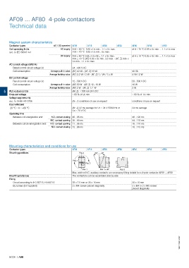
Mounting characteristics and conditions for use
Contactor types AF09 AF16 AF26 AF38 AF40 AF52 AF80
Mounting positions Pos. 2 +30° -30°
Pos. 4
Pos. 3
Pos. 1 Pos. 1 ± 30° Pos. 5
Max. add-on N.C. auxiliary contacts: see accessory fitting details for a 4-pole contactor AF09 ... AF80
Mounting distances The contactors can be assembled side by side
Fixing
On rail according to IEC 60715, EN 60715 35 x 7.5 mm or 35 x 15 mm 35 x 15 mm
By screws (not supplied) 2 x M4 screws placed diagonally 2 x M4 or 2 x M6 screws
placed diagonally
1SBC101991S0201
5/226 | ABB