
Page 488 - Motor_protection_and_control_Manual_motor_starters_ contactors
P. 488
UA16..RA … UA110..RA 3-pole contactors for capacitor switching
Unlimited peak current Î
Technical data
Main pole - Utilization characteristics according to IEC
Contactor types AC operated UA16..RA UA26..RA UA30..RA UA50..RA UA63..RA UA75..RA UA95..RA UA110..RA
Standards IEC 60947-1 / 60947-4-1 and EN 60947-1 / 60947-4-1
Rated operational voltage Ue max. 690 V
Rated frequency (without derating) 50 / 60 Hz
AC-6b Utilization category
Rated operational power AC-6b (1)
For air temperature close θ ≤ 40 °C 230-240 V 8 kvar 12.5 kvar 16 kvar 25 kvar 30 kvar 35 kvar 40 kvar 45 kvar
to contactor 400-415 V 12.5 kvar 22 kvar 30 kvar 40 kvar 50 kvar 60 kvar 70 kvar 80 kvar
440 V 15 kvar 24 kvar 32 kvar 50 kvar 55 kvar 65 kvar 75 kvar 85 kvar
500-550 V 18 kvar 30 kvar 34 kvar 55 kvar 65 kvar 75 kvar 85 kvar 95 kvar
690 V 22 kvar 35 kvar 45 kvar 72 kvar 80 kvar 100 kvar 120 kvar 130 kvar
θ ≤ 55 °C 230-240 V 7.5 kvar 11.5 kvar 16 kvar 24 kvar 27 kvar 30 kvar 35 kvar 40 kvar
400-415 V 12.5 kvar 20 kvar 27.5 kvar 40 kvar 45 kvar 50 kvar 60 kvar 70 kvar
440 V 13 kvar 20 kvar 30 kvar 43 kvar 48 kvar 53 kvar 65 kvar 75 kvar
5 Multi-step capacitor 500-550 V 16 kvar 25 kvar 34 kvar 50 kvar 60 kvar 65 kvar 75 kvar 82 kvar
bank scheme 690 V 21 kvar 31 kvar 45 kvar 65 kvar 75 kvar 80 kvar 105 kvar 110 kvar
θ ≤ 70 °C 230-240 V 6 kvar 9 kvar 11 kvar 20 kvar 23 kvar 25 kvar 30 kvar 35 kvar
400-415 V 10 kvar 15.5 kvar 19.5 kvar 35 kvar 39 kvar 41 kvar 53 kvar 60 kvar
440 V 11 kvar 17 kvar 20.5 kvar 37 kvar 42.5 kvar 45 kvar 58 kvar 70 kvar
500-550 V 12.5 kvar 20 kvar 25 kvar 46 kvar 50 kvar 55 kvar 70 kvar 78 kvar
690 V 17 kvar 26 kvar 32 kvar 60 kvar 65 kvar 70 kvar 85 kvar 100 kvar
Max. permissible peak current Î Unlimited
Short-circuit protection device for contactors
gG type fuse (2) 80 A 125 A 200 A 250 A
Max. electrical switching frequency 240 cycles/h
Electrical durability AC-6b Ue ≤ 440 V 250 000 operating cycles
500 V ≤ Ue ≤ 690 V 100 000 operating cycles
(1) For 220 V and 380 V, multiply by 0.9 the rated values at 230 V and 400 V respectively.
Example: 50 kvar / 400 V corresponding to 0.9 x 50 = 45 kvar/380 V.
(2) The fuse ratings given represent the maximum ratings ensuring type 1 coordination according to the definition of standard IEC 60947-4-1.
Main pole - Utilization characteristics according to UL / CSA
Contactor types AC operated UA16..RA UA26..RA UA30..RA UA50..RA UA63..RA UA75..RA UA95..RA UA110..RA
Power - 60 Hz
For air temperature close θ ≤ 40 °C 240 V 8 kvar 11 kvar 14 kvar 25 kvar 27.5 kvar 32 kvar 40 kvar 45 kvar
to contactor 480 V 16 kvar 22 kvar 28 kvar 50 kvar 55 kvar 64 kvar 80 kvar 95 kvar
600 V 20 kvar 27 kvar 35 kvar 62 kvar 70 kvar 80 kvar 100 kvar 120 kvar
Max. permissible peak Current Î Unlimited
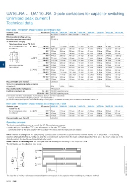
Operating principle
The front-mounted block mechanism of the UA..RA contactors ensures:
– early making of the auxiliary "PA" poles with respect to the main "PP" poles
– automatic return to the open position of the auxiliary "PA" poles after the main poles are closed.
When the coil is energized, the early making auxiliary poles connect the capacitor to the network via the set of 3 resistors. The damping
resistors attenuate the first current peak and the second inrush current when the main contacts begin to make. Once the main poles are in the
closed position, the auxiliary poles automatically break.
When the coil is de-energized, the main poles break ensuring the breaking of the capacitor bank.
The contactor can then begin a new cycle.
Coil voltage
Uc
R
A1 PP PA Aux. poles
PA
A2 Main poles
R
PP
C Total 1SBC101510S0201 - Rev. A
closing time
The insertion of resistors allows to damp the highest current peak of the capacitor when switching on, whatever its level.
5/288 | ABB