
Page 728 - Motor_protection_and_control_Manual_motor_starters_ contactors
P. 728
TF65 thermal overload relays – 22.0 to 67.0 A
Technical data
Main circuit – Utilization characteristics according to IEC/EN
Type TF65
Standards IEC/EN 60947-1, IEC/EN 60947-4-1, IEC/EN 60947-5-1
Rated operational voltage U e 690 V AC
Rated frequency 50/60 Hz
Trip class 10
Number of poles 3
Duty time 100%
Operating frequency without early tripping Up to 15 operations/h, see "Technical diagram – Intermittent periodic duty"
Rated impulse withstand voltage U imp 8 kV
Rated insulation voltage U 690 V
i
Auxiliary circuit according to IEC/EN
Type TF65
Rated operational voltage U e 600 V
Conventional free air thermal current I th N.C., 95-96 6 A
N.O., 97-98 4 A
Rated frequency DC, 50/60 Hz
Number of poles 1 N.O. + 1 N.C.
I / Rated operational current AC-15
e
acc. to IEC/EN 60947-5-1 for utilization category
7 110-120 V N.C., 95-96 3.00 A
N.O., 97-98 0.75 A
220-230-240 V N.C., 95-96 3.00 A
N.O., 97-98 0.75 A
440 V N.C., 95-96 0.75 A
N.O., 97-98 0.75 A
480-500 V N.C., 95-96 0.75 A
N.O., 97-98 0.75 A
I / Rated operational current DC-13
e
acc. to IEC/EN 60947-5-1 for utilization category
24 V N.C., 95-96 1.25 A
N.O., 97-98 1.25 A
110-120-125 V N.C., 95-96 0.55 A
N.O., 97-98 0.55 A
250 V N.C., 95-96 0.27 A
N.O., 97-98 0.27 A
Minimum switching capacity 17 V / 3 mA
Short-circuit protective device N.C., 95-96 6 A, gG Type Fuses
N.O., 97-98 4 A, gG Type Fuses
Rated impulse withstand voltage U 6 kV
imp
Rated insulation voltage U i 690 V
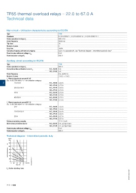
Technical diagram – Intermittent periodic duty
(Op/h)
140
120
100 a
switching frequency 80 t = 1.5 s
t = 0.5 s
a
60
a
t = 1 s
40
a
20 t = 3 s
a
t = 5 s
0 2CDC232004F0214
0 20 40 60 80 100 (%)
duty ratio
t : Motor starting time
a
2CDC106063C0201
7/14 | ABB