Page 933 - Motor protection and control Manual motor starters, contactors and overload relays
P. 933

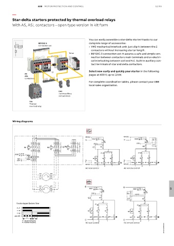
ABB  MOTOR PROTECTION AND CONTROL                                               12/99

          —
          Star-delta starters protected by thermal overload relays

          With AS, ASL contactors - open type version in kit form


                                                              You can easily assemble a star-delta starter thanks to our
                           BEY16C-3                           complete range of accessories:
           L      Y        Connection set                     •  VM3 mechanical interlock unit: just clip it between the 2
                                                               contactors without increasing starter length.
                                                Timer         •  BEY16C-3 connection set: it assures a safe and simple con-
                                                               nection between contactors main terminals and an electri-
                                                               cal interlocking between coil and N.C. built-in auxiliary con-
                                                               tact terminals of star and delta contactors.

                                                              Select now easily and quickly your starter in the following
                  AS                                          pages at 400 V, up to 11 kW.
                  ASL
                  Contactors
                                                              For complete coordination tables, please contact your ABB
                                                              local sales organization.

                                         CA3
                                         1-pole auxiliary
                                         contact block
                     T16
                     Thermal
                     overload relay


          Wiring diagrams


                                                           KM1:5/L3                   KM1:5/L3
                                                                   A                            A
                                                                RESET                        RESET M
                                                           Us      M   95             Us             95  O
                       1/L1  3/L2  5/L3  13  23  1/L1  3/L2  5/L3  21  1/L1  3/L2  5/L3  13  21  STOP  96  FR1  STOP  96  FR1  I
                     A1             A1       KM2  A1                   23                          KM1  23
                 KM1             KM3                            I     KM1
                     A2             A2          A2                     24                            24
                       2/T1  4/T2  6/T3  14  24  2/T1  4/T2  6/T3  22  2/T1  4/T2  6/T3  14  22  17  17
           RESET  A                                                   KT                        KT
              M     95  97                                              28    18                  28   18
                          FR1                                     13  13  22  22            13  13  22  22
             TEST   96  98                                       KM2KM1  KM2  KM3         KM2KM1  KM2  KM3
             STOP      2/T1  4/T2  6/T3                    Us     14  14  21  21      Us    14  14  21  21
                                                           N        A1  A1   A1    A1        A1   A1   A1   A1
                                                                               KM2  KT  N     KM1  KM3   KM2KT
                                                                  KM1  KM3
                                                           KM1:3/L2  A2  A2  A2    A2  KM1:3/L2  A2  A2  A2  A2
                                                                    L        Y               L         Y
                                                            AC local control          AC remote control
                            W1     W2
                            V1      V2
                            U1     U2
                            W1     W2                      +                         +
                            V1      V2                        RESET  A  95                  RESET  A                  12
                            U1     U2                            M                             M    95
                                                                STOP   96 FR1           O           96  FR1
                                                                                             STOP
                                                                       23
                                                             I       KM1                            23
                                                                       24               I         KM1
                                                                                                    24
            Function diagram Electronic Timer                           17                          17
                                                                  KT
                                                                                               KT
             A1-A2                                                  28    18                     28    18
                                                               13  13  22  22
                                                                                          13
             17-18                                           KM2  KM1  KM2  KM3          KM2 KM1  13  KM2  22  KM3 22
             17-28                                             14  14  21  21             14  14  21   21
           green LED                                             A1+  A1+  A1+  A1+         A1+  A1+   A1+  A1+
                   t1   t2                                    KM1  A2-  KM3  A2-  A2-  KM2 KT  A2-  KM1  A2-  KM3  A2-  A2-  KM2  KT  A2-
                                                           -                          -
                t1 = adjusted starting time                      L        Y                 L          Y
                t2 = transition time (50ms)                 DC local control          DC remote control
                                                                                                                 1SBC101288S0201
   928   929   930   931   932   933   934   935   936   937   938