
Page 932 - Motor protection and control Manual motor starters, contactors and overload relays
P. 932
12/98 ABB MOTOR PROTECTION AND CONTROL
—
Star-delta starters protected by thermal overload relays
With AS, ASL contactors - open type version in kit form
Application
Star-delta starting is the most common method to reduce the starting current of a motor.
L Y
This system can be used on all the squirrel cage motors, which are normally used in delta
connection. In this type of starting, it is recommended to choose motors having high start-
ing torque i.e. much higher than the resistive torque in order to reach sufficient high speed
when the motor is connected in star.
When starting:
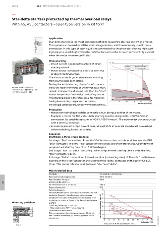
• Inrush current is reduced to a third of direct I /I n T/T n I = current In = nominal current
7
1SBC101207F0014 • Motor torque is reduced to a third or even less 6 T = torque I (delta) Tn = nominal torque
starting current
of direct starting torque.
Transient current is generated when switching 5
4
from star to delta connection.
During the initial starting phase ("star" connec- 3
AS09-30-10 + AS09-30-01 tion), the resistive torque of the driven load must
+ AS09-30-01 + BEY16C-3 + VM3 remain, irrespective of speed, less than the "star" 2 (mot
T∆or)
I
+ CT-SDS + CA3-10 + T16 (star)
motor torque until "star-delta" switching occurs. 1
(motor)
T ≻
This starting mode is therefore ideal for machines T r (resistive torque)
having low starting torque such as pumps, 0 20 40 60 80 100
centrifugal compressors, wood-working machines... Motor speed (%)
Precaution
• Motor nominal voltage in delta connection must be equal to that of the mains.
Example: a motor for 400 V star-delta starting must be designed for 400 V in "delta"
connection. Its usual designation is "400 V / 690 V motor". The motor must be constructed
with 6 terminal windings
• In order to prevent a high current peak, at least 85 % of nominal speed must be reached
before switching from star to delta
Sequence
Starting is a three-stage process:
1st stage: "Star" connection - Press the "On" button on the control circuit to close the KM2
"Star" contactor. The KM1 "line" contactor then closes and the motor starts. Countdown of
programmed starting time (6 to 10 s) then begins.
2nd stage: "Star" to "Delta" switching - when programmed starting time is over, the KM2
"Star" contactor opens.
3rd stage: "Delta" connection - A transition time (or dwelling time) of 50 ms is fixed between
opening of the "star" contactor and closing of the "delta" contactor by the use of CT-SDS
timer. This prevent short-circuit between "star" and "delta".
Main technical data
Standards IEC 60947-4-1 / EN 60947-4-1
Rated operational voltage Ue max. 690 V - 50/60 Hz
Rated insulation voltage Ui 690 V
according to IEC 60947-4-1
Air temperature close to the device ≤ 60 °C
12
Degree of protection IP20
Switching frequency 70
Switching frequency/hour, according to acceleration time and 60
load factor. Respect of the following conditions enables ta = 5 s
utilization of the starter without excessive overheating of the 50
connections or nuisance tripping of the thermal overload relay.
Mounting positions Example: 40 ta = 8 s
– Switching frequency = 15 starts/hr Switching frequency (ops/h) 30 ta = 10 s
– Motor starting time "Ta" = 7 s (use 8 s curve) ta = 12 s
– Maximum load factor = 63 %. 20 ta = 15 s
This corresponds to a 4-minute operating cycle (15 starts/hr) 10 ta = 20 s
with 7 seconds acceleration, 2.5 minutes operation and 1.5
minutes rest. 0
0 10 20 30 40 50 60 70 80 90 100
Duty ratio (%) 1SBC101288S0201
Duty ratio in %, Ta: acceleration time
Pos. 1