
Page 928 - Motor protection and control Manual motor starters, contactors and overload relays
P. 928
12/94 ABB MOTOR PROTECTION AND CONTROL
—
DOL & reversing starters protected by thermal overload relays
With AS, ASL contactors - open type version in kit form
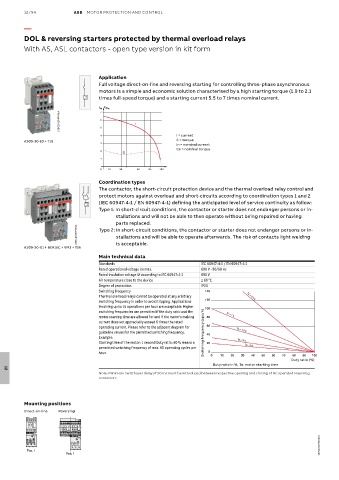
Application
Full voltage direct-on-line and reversing starting for controlling three-phase asynchronous
motors is a simple and economic solution characterised by a high starting torque (1.9 to 2.1
times full-speed torque) and a starting current 5.5 to 7 times nominal current.
I C
/In 7 /Cn
1SBC101204F0014 6 5 I
4 I = current
AS09-30-10 + T16 C = torque
3
In = nominal current
Cn = nominal torque
2
C
1
0 10 30 60 80 100
Coordination types
The contactor, the short-circuit protection device and the thermal overload relay control and
protect motors against overload and short-circuits according to coordination types 1 and 2
(IEC 60947-4-1 / EN 60947-4-1) defining the anticipated level of service continuity as follow:
Type 1: In short-circuit conditions, the contactor or starter does not endanger persons or in-
stallations and will not be able to then operate without being repaired or having
parts replaced.
1SBC101205F0014 Type 2: In short-circuit conditions, the contactor or starter does not endanger persons or in-
stallations and will be able to operate afterwards. The risk of contacts light welding
AS09-30-01 + BER16C + VM3 + T16 is acceptable.
Main technical data
Standards IEC 60947-4-1 / EN 60947-4-1
Rated operational voltage Ue max. 690 V - 50/60 Hz
Rated insulation voltage Ui according to IEC 60947-4-1 690 V
Air temperature close to the device ≤ 60 °C
Degree of protection IP20
Switching frequency 140
Thermal overload relays cannot be operated at any arbitrary Ta = 0.5 s
switching frequency in order to avoid tripping. Applications 120
involving up to 15 operations per hour are acceptable. Higher 100
switching frequencies are permitted if the duty ratio and the
motor starting time are allowed for and if the motor's making 80 Ta = 1 s
current does not appreciably exceed 6 times the rated
operating current. Please refer to the adjacent diagram for 60
guideline values for the permitted switching frequency. Switching frequency (ops/h) 40 Ta = 1.5 s
Example:
Starting time of the motor: 1 second Duty ratio: 40 % means a 20 Ta = 3 s
permitted switching frequency of max. 60 operating cycles per Ta = 5 s
hour. 0 0 10 20 30 40 50 60 70 80 90 100
Duty ratio (%)
Duty ratio in %, Ta: motor starting time
12
Note: Minimum switchover delay of 50 ms must be introduced between respective opening and closing of AC operated reversing
contactors
Mounting positions
Direct-on-line Reversing
1SBC101275S0201
Pos. 1
Pos. 1