
Page 108 - 1SBC104119C0202_MainCatalog_R contactors
P. 108
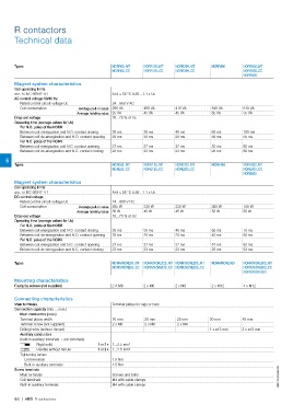
R contactors
Technical data

Types                                                          NORR63..MT       NORR125..MT      NORR200..MT      NORR400       NORR800..MT
                                                               NORR63..CC       NORR125..CC      NORR200..CC                    NORR800..CC
                                                                                                                  540 VA        NORR800
Magnet system characteristics                                                                    410 VA           65 VA
                                                                                                 45 VA                          610 VA
Coil operating limits                                                                                             60 ms         55 VA
                                                                                                 40 ms            50 ms
acc. to IEC 60947-4-1                                          At θ ≤ 55 °C 0.85…1.1 x Uc        20 ms            55 ms         100 ms
                                                                                                 37 ms            28 ms         55 ms
AC control voltage 50/60 Hz                                                                      23 ms            NORE400       85 ms
                                                                                                                                60 ms
Rated control circuit voltage Uc                               24…550 V AC                       NORE200..MT      360 W
                                                               290 VA                            NORE200..CC      50 W          NORE800..MT
Coil consumption                        Average pull-in value  25 VA            460 VA                                          NORE800..CC
                                                               20...75 % of Uc  45 VA            330 W            60 ms         NORE800
                                        Average holding value                                    45 W             45 ms
                                                                                                                  57 ms         700 W
Drop-out voltage                                                                                 40 ms            28 ms         55 W
                                                                                                 20 ms
Operating time (average values for Uc)                                                           37 ms                          70 ms
                                                                                                 23 ms                          50 ms
For N.O. poles of the NORR                                                                                                      62 ms
                                                                                                                                53 ms
Between coil energization and N.O. contact closing             30 ms            30 ms
                                                               20 ms            20 ms
Between coil de-energization and N.O. contact opening
                                                               27 ms            27 ms
For N.C. poles of the NORR                                     23 ms            23 ms

Between coil energization and N.C. contact opening

Between coil de-energization and N.C. contact closing

6                                                              NORE63..MT       NORE125..MT
      Types                                                    NORE63..CC       NORE125..CC

Magnet system characteristics

Coil operating limits

acc. to IEC 60947-4-1                                          At θ ≤ 55 °C 0.85…1.1 x Uc

DC control voltage

Rated control circuit voltage Uc                               24…600 V DC
                                                               265 W
Coil consumption                        Average pull-in value  30 W             330 W
                                                               10...75 % of Uc  45 W
                                        Average holding value

Drop-out voltage

Operating time (average values for Uc)

For N.O. poles of the NORR

Between coil energization and N.O. contact closing             30 ms            30 ms
                                                               20 ms            20 ms
Between coil de-energization and N.O. contact opening
                                                               27 ms            27 ms
For N.C. poles of the NORR                                     23 ms            23 ms

Between coil energization and N.C. contact opening

Between coil de-energization and N.C. contact closing

Types                                                          NORR/NORE63..MT NORR/NORE125..MT NORR/NORE200..MT  NORR/NORE400  NORR/NORE800..MT
                                                               NORR/NORE63..CC NORR/NORE125..CC NORR/NORE200..CC                NORR/NORE800..CC
Mounting characteristics                                                                                                        NORR/NORE800

Fixing by screws (not supplied)                                2 X M6           2 x M6           2 x M8           2 x M12       4 x M12

Connecting characteristics                                     Terminal plates for lugs or bars

Main terminals                                                 16 mm            20 mm            25 mm            30 mm         48 mm
Connection capacity (min. ... max.)                            2 x M6           2 x M6           2 x M8           -             -
                                                               -                -                -                1 x ø13 mm    2 x ø13 mm
    Main conductors (poles)
    Terminal plates width                            1 or 2 x 1...2.5 mm²                                                                         1SBC104024S0201
    Terminal screw (not supplied)                    1 or 2 x 1...2.5 mm²
    Drilling holes (without thread)
    Auxiliary conductors                                        1.5 Nm
    (built-in auxiliary terminals + coil terminals)             1.5 Nm

                  Rigid solid                                   Screws and bolts
                  Flexible without ferrule                      M4 with cable clamps
    Tightening torque                                           M4 with cable clamps
       Coil terminals
       Built-in auxiliary terminals
Screw terminals
    Main terminals
    Coil terminals
    Built-in auxiliary terminals

6/6 | ABB R contactors