
Page 84 - Current & voltage sensors catalog
P. 84
VS2000B ... VS4200B railway voltage sensors
For rolling stock and infrastructure
Technical data
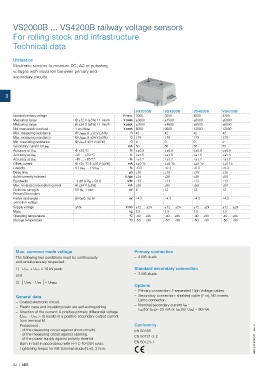
Utilisation
Electronic sensors to measure DC, AC or pulsating
voltages with insulation between primary and
secondary circuits.
3
VS2000B VS3000B VS4000B VS4200B
Nominal primary voltage V r.m.s. 2000 3000 4000 4200
Measuring range @ ±12 V (±5%) / 1 min/h V peak ±3000 ±4500 ±6000 ±6000
Measuring range @ ±24 V (±5%) / 1 min/h V peak ±3000 ±4500 ±6000 ±6000
Not measurable overload 1 sec/hour V peak 6000 9000 12000 12000
Max. measuring resistance @ U PMAX & ±12 V (±5%) Ω 42 42 42 42
Max. measuring resistance @ U PMAX & ±24 V (±5%) Ω 179 179 179 179
Min. measuring resistance @ U PN & ±24 V (±5%) Ω 0 0 0 0
Secondary current at U PN mA 50 50 50 50
Accuracy at U PN @ +25 °C % ≤±0.9 ≤±0.9 ≤±0.9 ≤±0.9
-25 … +70 °C % ≤±1.5 ≤±1.5 ≤±1.5 ≤±1.5
Accuracy at U PN
Accuracy at U PN -40 … +85 °C % ≤±1.7 ≤±1.7 ≤±1.7 ≤±1.7
Offset current @ +25 °C & ±24 V (±5%) mA ≤±0.15 ≤±0.15 ≤±0.15 ≤±0.15
Linearity 0.1U PN … 1.5U PN % ≤0.3 ≤0.3 ≤0.3 ≤0.3
Delay time μs ≤10 ≤10 ≤10 ≤10
dv/dt correctly followed V / μs ≤24 ≤36 ≤48 ≤50
Bandwidth -3 dB & R M = 50 Ω kHz ≤13 ≤13 ≤13 ≤13
Max. no-load consumption current @ ±24 V (±5%) mA ≤50 ≤50 ≤50 ≤50
Dielectric strength 50 Hz, 1 min kV 8 12 12 12
Primary/Secondary
Partial discharges : @10pC, 50 Hz kV ≥4.3 ≥4.3 ≥4.3 ≥4.3
extinction voltage
Supply voltage ±5% V DC ±12 … ±24 ±12 … ±24 ±12 … ±24 ±12 … ±24
Mass kg 1.5 1.5 1.5 1.5
Operating temperature °C -40 … +85 -40 … +85 -40 … +85 -40 … +85
Storage temperature °C -50 … +90 -50 … +90 -50 … +90 -50 … +90
Max. common mode voltage Primary connection
The following two conditions must be continuously – 2 M5 studs
and simultaneously respected:
1) U HT+ + U HT- ≤ 10 kV peak Standard secondary connection
and – 3 M5 studs
2) | U HT+ - U HT- | ≤ U PMAX
Options
– Primary connection: 2 separated High Voltage cables.
General data – Secondary connection: shielded cable (2 m), M5 inserts,
Lemo connector.
– Coated electronic circuit.
– Nominal secondary current I SN :
– Plastic case and insulating resin are self-extinguishing.
I SN (for U PN)= 20 mA or I SN (for U PN) = 80 mA.
– Direction of the current: A positive primary differential voltage
(U HT+ - U HT- > 0) results in a positive secondary output current
from terminal M.
– Protections : Conformity
- of the measuring circuit against short-circuits. EN 50155
- of the measuring circuit against opening. EN 50121-3-2
- of the power supply against polarity reversal. 1SBC140060S0201 - Rev. A
– Burn-in test in accordance with FPTC 404304 cycle. EN 50124-1
– Tightening torque for M5 terminal studs (N.m): 2 N.m.
82 | ABB