Page 155 - EPR Catalog 2015
P. 155

Thermistor motor protection relays                                                                                                                                       2
Operating controls

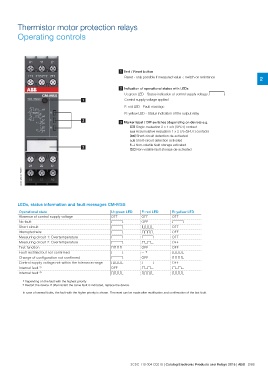
                                                                                           1 Test / Reset button
                                                                                               Reset - only possible if measured value < switch-on resistance

                                                                                           2 Indication of operational states with LEDs

                                                                 U: green LED - Status indication of control supply voltage V

                                                         1 Control supply voltage applied
                                                                                               F: red LED - Fault message
                                                                                               R: yellow LED - Status indication of the output relay

                                                         2 3 Marker label / DIP switches (depending on device) e.g.
                                                                                                            i Single evaluation 2 x 1 c/o (SPDT) contact
                                                                                                            j Accumulative evaluation 1 x 2 c/o (SPDT) contacts
                                                                                                            y Short-circuit detection de-activated
                                                                                                            x Short-circuit detection activated
                                                                                                            f Non-volatile fault storage activated

                                                         3 e Non-volatile fault storage de-activated

2CDC 253 001 F0015

LEDs, status information and fault messages CM-MSS

Operational state                                      U: green LED  F: red LED  R: yellow LED
Absence of control supply voltage                      OFF           OFF         OFF
No fault                                               V             OFF         V
Short circuit                                          V             Y           OFF
Interrupted wire                                       V             Z           OFF
Measuring circuit 1: Overtemperature                   V             V           OFF
Measuring circuit 2: Overtemperature                   V             W           OFF
Test function                                          X             OFF         OFF
Fault rectified but not confirmed                      V             -- 1)       X
Change of configuration not confirmed                  V             OFF         X
Control supply voltage not within the tolerance range  X             V           OFF
Internal fault 2)                                      OFF           W           W
Internal fault 2)                                      X             X           X

                    1) Depending on the fault with the highest priority
                    2) Restart the device. If after restart the same fault is indicated, replace the device.

                    In case of several faults, the fault with the higher priority is shown. The reset can be made after rectification and confirmation of the last fault.

                                                       2CDC 110 004 C0210 | Catalog Electronic Products and Relays 2015 | ABB 2/88
   150   151   152   153   154   155   156   157   158   159   160